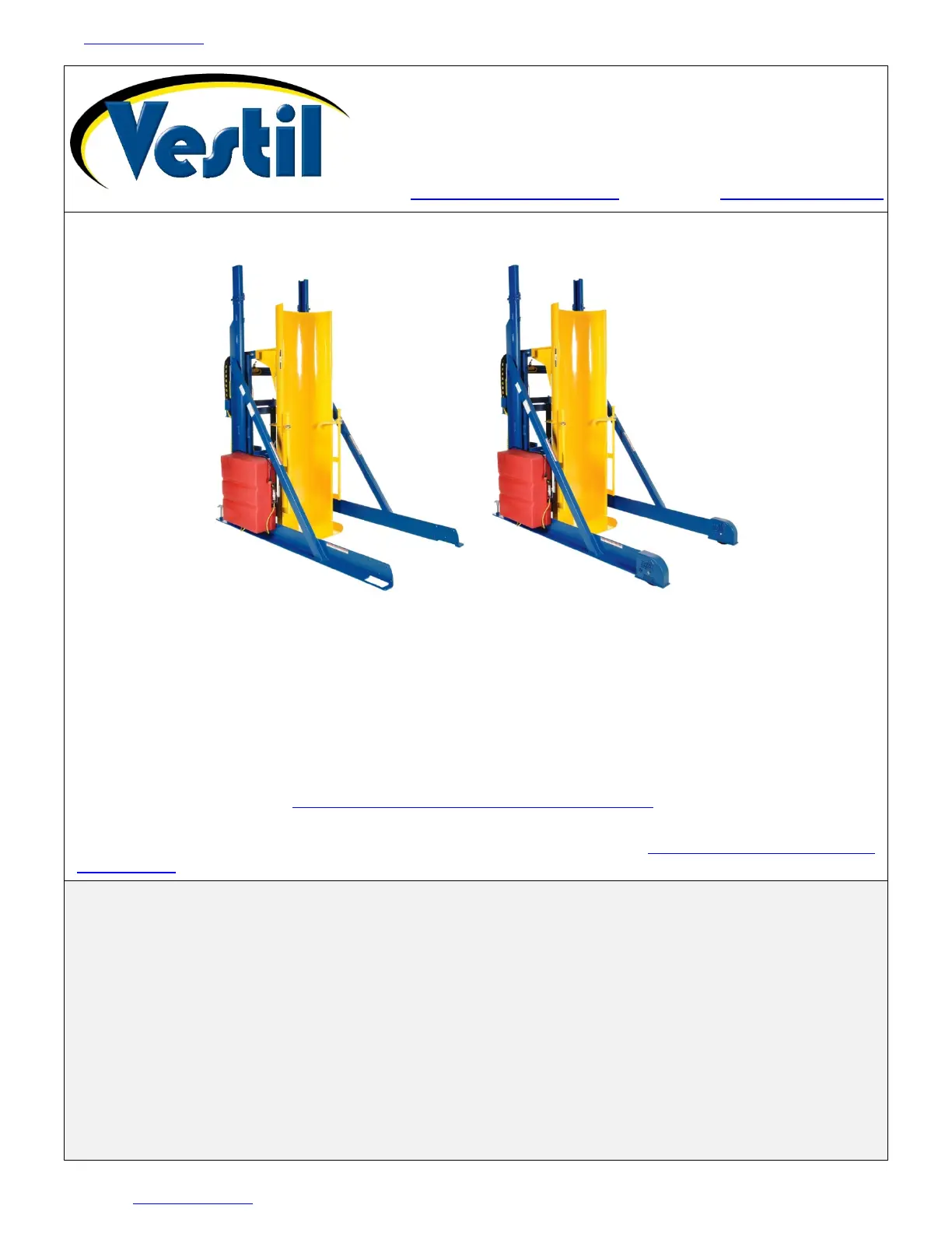
Table of Contents 2/4/2022 HLD MANUAL
Table of Contents Copyright 2010 Vestil Manufacturing Corp. Page 1 of 19
HLD-SERIES HYDRAULIC DRUM DUMPERS
Receiving Instructions
After delivery, remove the packaging from the product. Inspect the product closely to determine
whether it sustained damage during transport. If damage is discovered, record a complete description of
it on the bill of lading. If the product is undamaged, discard the packaging.
NOTE: The end-user is solely responsible for confirming that product design, use, and maintenance comply
with laws, regulations, codes, and mandatory standards applied where the product is used.
Technical Service & Replacement Parts
For answers to questions not addressed in these instructions and to order replacement parts, labels,
and accessories, call our Technical Service and Parts Department at (260) 665-7586. The Department can
also be contacted online at https://www.vestil.com/page-parts-request.php
.
Electronic Copies of Instruction Manuals
Additional copies of this instruction manual may be downloaded from
https://www.vestil.com/page-
manuals.php.
Vestil Manufacturing Corp.
2999 North Wayne Street, P.O. Box 507, Angola, IN 46703
Telephone: (260) 665-7586 -or- Toll Free (800) 348-0868
Fax: (260) 665-1339
www.vestilmfg.com e-mail: info@vestil.com
Specifications…………………….……………....
Fig. 1: Installation Diagram…………………………
Signal Words…………………….………………..
Fig. 2A: HLD Side View………………………………
Safety Instructions………………………………..
Fig. 2B: Drum-Engaging Clamp Assembly……….
Installing the Drum Dumper……………………
Fig. 3A: Handheld Controller Functions………….
Record of Satisfactory Condition……………
Fig. 3B: Handheld Controller……………………….
Operating the Drum Dumper………………….
Fig. 4: Limit Switch Effect on Dumping Angle…..
Inspections………………………………………..
Fig. 5: 115VAC Electrical Circuit Diagram……….
Power Unit Operation……………………………
Fig. 6: 208-230VAC Electrical Circuit Diagram….
Sequence of Operation………………………..
Fig. 7: 230/460VAC Electrical Circuit Diagram....
Operation Issues and Solutions………………..
Fig. 8: Hydraulic Circuit Diagram………………….
Removing Air from the System……………….
Figs. 9-12: Exploded Views & Bills of Materials…..
Troubleshooting Guide………………………….
Fig. 13: Labeling Diagram………………..…………
Limited Warranty…………………………………