Vimar 01875.120 Manual
Vimar
Ikke kategoriseret
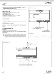
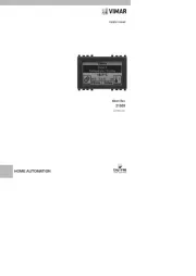
01875.120

| Mærke: | Vimar |
| Kategori: | Ikke kategoriseret |
| Model: | 01875.120 |
Har du brug for hjælp?
Hvis du har brug for hjælp til Vimar 01875.120 stil et spørgsmål nedenfor, og andre brugere vil svare dig
Ikke kategoriseret Vimar Manualer
2 September 2025
25 August 2025
25 August 2025
25 August 2025
20 August 2025
25 Juli 2025
25 Juli 2025
25 Juli 2025
24 Juli 2025
24 Juli 2025
Ikke kategoriseret Manualer
- Reltech
- ATN
- VigilLink
- Viewsonic
- Integra
- EmberGlo
- Carlsbro
- Juki
- Andersson
- Induction Dynamics
- BluDento
- Zega
- CoolerMaster
- Heusinkveld
- Epcom
Nyeste Ikke kategoriseret Manualer

21 December 2025

21 December 2025

21 December 2025

21 December 2025

21 December 2025

21 December 2025

21 December 2025

21 December 2025

20 December 2025

20 December 2025