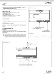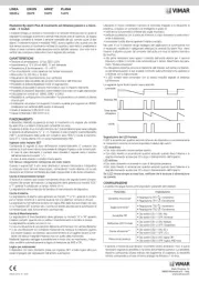
Custodia in materiale termoplastico grigio, predi
sposto per montaggi su quadri con barra DIN ad
omega con un ingombro di 12 moduli.
- Alimentazione: 230V c.a. 50/60 Hz
- Corrente nominale: 0,27 A
- Realizzazione su schede intercambiabili per una
- Uscita serratura: 15V rettificati, 1A a ciclo inter
mittente (30 s ON, 180 s OFF), 0,25A servizio
continuo per illuminazione tasti (3x24V 3W max).
PROTEZIONI INSERITE NELL’ALIMENTATORE:
- Avvolgimento primario trasformatore: PTC
- Avvolgimento secondario alimentazione serra
- Protezione elettronica interna e fonica citofoni:
Nota: Non asportare il portellino di protezione della
Dimensioni: 210x110x72,8 mm
In caso di cortocircuito i dispositivi di protezione
(PTC) in ter ven go no togliendo la tensione di rete e:
eliminato il cortocircuito, oc cor re at ten de re alcuni
minuti per permettere il raffreddamento del di spo-
si ti vo di protezione affinchè l’apparecchio torni a
fun zio na re re go lar men te.
PRINCIPIO Dl FUNZIONAMENTO DELL’IM
PIANTO SENZA SE GRE TO Dl CON VER SA-
ZIO NE, UTILIZZANDO CITOFONI 8877 - 900/137
Premendo sulla targa esterna il pulsante corri
spondente all’utente de si de ra to, viene attivata la
suoneria del citofono chiamato. Tutti i citofoni sono
sempre in co mu ni ca zio ne con il posto esterno
senza segreto di con ver sa zio ne e possono azionare
in qualsiasi momento la serratura elettrica.
PRINCIPIO DI FUNZIONAMENTO DELL’IM
PIANTO CON SEGRETO DI CONVERSAZIONE,
UTILIZZANDO CITOFONI 875/837 - 900/837 -
Premendo sulla targa esterna il pulsante corri
spondente all’utente de si de ra to, viene attivata la
suoneria del citofono ed una memoria elettronica
predispone l’inserzione del l’ap pa rec chio stesso.
Nello stesso tempo l’even tua le citofono preceden
temente inserito viene automaticamente escluso.
Quando l’utente chiamato solleva il microtelefono
può co mu ni ca re con l’esterno con assoluto segreto
Premendo il pulsante apriporta il citofono stesso
N.B. L’alimentatore 6837 può produrre due tipi di
nota elet tro ni ca: la prima (P1) viene utilizzata nor
malmente con la chiamata dal l’ester no, mentre la
seconda (P2) può essere usata collegando un pul
sante fuoriporta e predisponendo un filo in più sul
montante dei citofoni (vedi variante 1). Nel citofono
900/837 è possibile attivare la serratura anche se
il citofono non è stato chiamato dall’esterno. Per
fare ciò, spostare il filo dalla posizione AC alla po
Per diminuire l’intensità della chiamata negli
900/837, spostare, nel circuito stampato, il filo dal
connettore 6A al connettore 6B. Nel citofono 6201
togliere il ponticello“A” ed inserire la sche da 7155.
- Apertura diretta della serratura in qualsiasi mo
mento: po si zio na re il connettore nella po si zio ne
- Apertura della serratura dopo la chia ma ta: spo-
sta re nel ci to fo no il connettore da “SD” ad “SR” .
TECHNICAL CHARACTERISTICS
Power supply in grey ABS housing; preset for
mounting on cases with 12-module DIN support.
- 230V A.C. 50/60 Hz supply
- Interchangeable cards for quick maintenance.
- Removable terminal blocks.
- Door lock output: 15V rectified D.C. 1A intermit
tent cycle (30 s ON, s OFF), 0.25A continu180 -
ous duty for push-button illumination (3x24V 3W
PROTECTIONS ON POWER SUPPLY:
- Primary coil of transformer: PTC
- Secondary coil for lock supply: PTC
- Internal electronic protection and protection of
interphone audio line: PTC
Note: Do not remove the protection flap from the
Dimensions: 210x110x72,8 mm
In the event of a short-circuit, the protection circuit
removes the mains voltage until the fault is rectified.
After eliminating the short-circuit, it is necessary to
wait for a few minutes to allow cooling of the pro
tective device, so that the power supply may start
OPERATING PRINCIPLE OF INSTALLATION
WITHOUT CONVERSATION PRIVACY USING
INTERPHONES 8877 - 900/137 - 6201.
When the push-button corresponding to the user re
quired is pressed on the entrance panel, the chime
of the called interphone is activated, called will
sound. All the interphones are always in commu
nication with the outdoor unit without conversation
privacy, and the electric lock may be operated at
OPERATING PRINCIPLE OF INSTALLATION
WITH CONVERSATION PRIVACY, USING INTER
PHONES 875/837 - 8873 - 900/837 - (6201 + 7155).
Press the push-button corresponding to the us
er’s number on the entrance panel: the interphone
chime is activated and an electronic memory sys
tem activates the interphone. At the same time, any
previously activated interphone is automatically
When the called user lifts the interphone handset,
he or she can communicate with the outside in com
The interphone is excluded when the door-opening
N.B. Power supply 6837 can produce two electronic
notes: the first (P1) is normally used for calls from
outside; the second (P2) may be used by connect
ing a push-button outside the apartment door and
presetting an extra wire on interphone cable riser
With 900/837 the lock can be activated even if the
interphone has not been called from outside. To do
this, move the wire from position AC to position AS.
To reduce the intensity of caall in Arts. 900/837,
transfer wire, on the printed circuit board, from con
nector 6A to connector 6B.
Disconnect jumper “A” on interphone 6201 and
connect card 7155. Function settings for card 7155:
- Direct door lock release in any istant: insert the
- Door lock release after call: insert the wire in con
Il manuale istruzioni è scaricabile dal sito www.
The instruction manual is downloadable from the
CARACTÉRISTIQUES TECHNIQUES
Alimentation avec boîtier en matière thermoplas
tique grise; prédisposée pour montage sur barre
- Alimentation: 230V c.a. 50/60 Hz
- Courant nominal : 0,27 A
- Réatisation sur fiches interchangeables pour as
- Sortie gâche: 15V rectifiés, 1A à cycle intermit
tent (30 s ON, s OFF), 0,25A service continu 180
pour éclairage boutons-poussoirs (3x24V 3W
PROTECTIONS INSER ES DANS L’ALIMENTAÉ
- Enroulement primaire transformateur: PTC
- Enroulement secondaire pour alimentation
- Protection électronique interne et protection de la
ligne de phonie des postes d’appartement: PTC
Remarque : Ne pas démonter le volet de protection
du logement des potentiomètres.
Dimensions: 210x110x72,8 mm
En cas de court-circuit une protection thermique
(PTC) intervient en coupant la tension du reséau
Après avoir éliminé le court-circuit, il faut attendre
quelques minutes pour permetre le refroidissement
du dispositif de protection, pour que l’alimentation
recommence a fonctionner régulièrement.
PRINCIPE DE FONCTIONNEMENT DE L’ INS
TALLATION SANS SECRET DE CONVER-
SATION, EN UTILISANT LES POSTES 8877
En appuyant sur le bouton-poussoir de la plaque
de rue correspondant à l’ usager désiré, la sonne
rie électronique du poste appelé est activée. Tous
les postes sont toujours en communication avec
la plaque de rue sans secret de conversation et la
gâche électrique peut être actionnée à tout moment.
PRINCIPE DE FONCTIONNEMENT DE L’INSTAL
LATION AVEC SECRET DE CONVERSATION,
EN UTILISANT LES POSTES 875/837 - 8873 -
En appuyant sur le bouton-poussoir de la plaque
de rue correspondant à l’usager désiré, la sonnerie
électronique est activée, et une mémoire électro
nique permet l’insertion du poste d’appartement.
En même temps le poste précedemment inséré est
désactivé. Quand l’usager soulève le combiné, il est
en communication avec l’extérieur, avec secret de
conversation. En appuyant sur le bouton-poussoir
ouvre-porte, le poste est désactivé.
N.B L’alimentation 6837 peut produire deux signaux
acoustiques différents: le premier (P1) pour l’appel
de l’extérieur, le deuxième (P2) peut être utilisé
en raccordant un poussoir à la porte de palier de
l’appartement (en prévoyant un fil supplémentaire
sur la colonne mon tan te des postes d’appartement
(voir variante1). L’article 900/837 permet d’activer
la gâche même lorsque le poste n’a pas été appelé
depuis l’extérieur. Dans ce cas, déplacer le fil de
la position AC à la position AS. Pour diminuer le
volume d’appel dans les 900/837, deplacer, dans le
circuit imprimé, le fil raccordé au connecteur 6A sur
Enlever le pontage “A” sur le poste d’appartement
6201 et monter la carte 7155. Fonctions de la carte
- Ouverture directe de la gâche dans n’importe
quel moment: mettre le connecteur en position
- Ouverture de la gâche après l’appel: déplacer
sur le poste d’appartement le connecteur “SD”
Netzgerat mit grauem ABS-Gehäuse. Vorbereitet
für Montage auf DlN-Schiene.
- 230V~ 50/60 Hz Versorgung
- Austauschbare Karten fur schnelle Wartung.
- Abnehmbare Klemmenblocke.
- Türöffnersausgang: 15V berichtigt, 1A ausset
zender Zyklus (30 s ON, s OFF, 0,25A stän180 -
diger Betrieb für Tastenbeleuchtung (3x24V 3W
EINGEBAUTE SIGHERUNGEN IM NETZGERÄT:
- PTC fur Primärwicklung des Netztrafos.
- Zweite Sekundärspule für Türoffnerversorgung:
- Eingebaute elektronische Sicherung. (Shutz bei
Kurzschiuß der internen Sprechverbindung):
Hinweis: Die Schutzklappe der Potentiometer nicht
Abmessungen: 210x110x72,8 mm
Im Fall eines Kurzschiußes wird die Netzwechsel
spannung für die Dauer des Fehlers abgeschaltet.
Nach Entfernen des Kurzsclußes, ist es notwendig
einige Minuten zu warten, bis das Netzgerät wieder
FUNKTIONSWEISE DER SPRECHANLAGE
OHNE MITHORSPERRE BEI VERWENDUNG
DER HAUSTELEFONE 8877 - 900/137 - 6201.
Drücken Sie am Klingeltableau die Taste die dem
gewünschten Teilnehmer zugeordnet ist. Das Läut
werk der Haustelefon wird aktiviert.
Alle Haustelefone sind ohne Mithörsperre, stets mit
dem Klingeltableau verbunden und können jeder
zeit den elektrischen Türöffner betätigen.
FUNKTIONSWEISE DER SPRECHANLAGE MIT
MITHÖRSPERRE BEI VERWENDUNG DER HAU
STELEFONE 875/837 - 8873 - 900/837 - (6201 +
Drücken Sie am Klingeltableau die Taste die dem
gewünschten Teilnehmer zugeordnet ist. Das Läut
werk der Haustelefon wird aktiviert und ein elektro-
nisches Speichersystem aktiviert das Haustelefon.
Gleichzeitig werden eventuelle vorher aktivierte
Haustelefone* abgeschalten. Hebt der angerufene
Teilnehmer den Hörer ab, ist er mit der Außenstelle
Das Haustelefon wird durch Drücken der Türöffner
N.B. Das Netzgerät 6837 erzeugt zwei verschie
dene elektronische Tonfolgen: die erste Tonfolge
(P1) wird normalerweise für Rufe von der Außen
stelle verwendet: die zweite (P2) kann für eine vor
der Wohnungstüre angebrachte Klingeltaste* ver
wendet werden. Hierfür muß aber eine zusätzliche
Ader vorgesehen werden (siehe Sonderschaltung
1). Mit Artikel 900/837 kann der Türoffner auch dann
betätigt werden, wenn kein Ruf von außen erfolgt
ist. Hierzu den Drath aus der Position AC in die Po
sition AS umlegen.Um die Lautstärke des Ruftons in
den 900/837 zu verringern, muß man den Anschluß
von Kupplungskonnector 6A auf Kupplungskonnec
tor 6B der gedruckter Schaltung umstecken. Ent-
fernen Sie beim Haustelefon 6201 die Brücke “A”
und setzen Sie die Karte 7155 ein. Mit Karte 7155:
- Direkte Schloßfreigabe zu jeder Zeit: Positionie
ren Sie den Verbinder auf “SD”.
- Schloßfreigabe nach dem Ruf: Versetzen Sie im
Haustelefon den Verbinder von “SD” nach “SR” .
Die Bedienungsanleitung ist auf der Website
www.vimar.com zum Download verfügbar
Télécharger le manuel d’instructions sur le site
36063 Marostica VI - Italy