36063 Marostica VI - Italy
Lettore di carte a transponder per installazione all’esterno della stanza,
standard KNX, 2 uscite a relè NO 4 A 24 V~, 2 ingressi, alimentazione
12-24 V~ 50-60 Hz e 12-24 V d.c. (SELV), grigio, - 3 moduli.
Il dispositivo consente, attraverso carte a transponder, il controllo degli accessi nei locali
dove esso è installato esternamente. Il lettore a transponder è provvisto di due relè per il
controllo della serratura della porta, per il comando di una luce di cortesia, o per altri usi
ancora; il dispositivo è inoltre provvisto di due ingressi per il collegamento di apparec-
chiature elettriche di tipo ON/OFF (ad esempio per il controllo dello switch di porta aperta
o chiusa, di un contatto magnetico per segnalazione finestra aperta o chiusa, allarme
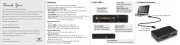
tirante bagno, ecc.). Sul frontale del lettore sono presenti quattro led ognuno associato
un’icona per la segnalazione dei seguenti stati:
- Accesso (accesso consentito o accesso negato);
- Stato cliente (camera occupata o non disturbare);
- Stato chiamate (richiesta soccorso da tirante bagno, chiamata cameriera, ecc.).
- Stato servizi (rifare camera, ecc.);
Il lettore a transponder è in grado di dialogare con altri componenti EIB/KNX mediante
• Tensione di alimentazione:
- sull’alimentazione (a 12-24 V ): 130 mA max
- alimentazione (12-24 V )
- ingressi digitali per 2 contatti NO o NC (privi di potenziale, SELV)
- uscite per 2 relè NO (24 V SELV 4 A cos 1; 24 V~ SELV 2 A cos 0,6)~
• Range di frequenza: 13,553-13,567 MHz
• Potenza RF trasmessa: < 60 dBμA/m
• Temperatura di funzionamento: -5 °C - +45 °C (uso interno)
• Questo apparecchio contiene solo circuiti SELV che devono essere mantenuti separati
da circuiti a tensione pericolosa
La configurazione del lettore, dell’indirizzo fisico, dei parametri (ingressi contatti NO o NC,
uscite relè normali o temporizzate, ecc.), avviene mediante il software ETS. Nel caso in
cui nel lettore a transponder venga caricato un applicativo ETS non corretto, lampeg-
geranno sia il led rosso posto sul retro del dispositivo che i led frontali 2, 3 e 4 (errore
di “device type”). Per ripristinare la configurazione desiderata, caricare nel dispositivo
l’applicativo ETS corretto.
La lettura della carta avviene posizionando la stessa di fronte al lettore che verifica
- “ ” (se coerente o meno);codice impianto
- campo “ ” (se abilitato verifica se la validità è scaduta o meno);data
- “ ” (verifica tutti i codici ad essa abbinati e abilitati quali codice cliente, codice password
di servizio, fasce orarie).
IMPORTANTE: I lettori a transponder vanno alimentati separatamente da tutti gli
altri carichi (elettroserrature, lampade, teleruttori,ecc.) mediante un trasformatore
16887 a loro dedicato le cui uscite andranno utilizzate esclusivamente per questi
Importante: La lunghezza del cavo per il collegamento degli ingressi non deve superare
N.B. In fase di installazione prevedere lunghezze di collegamento dei cavi che consen-
tano l’estrazione del dispositivo dalla scatola da incasso in modo tale da poter accedere
al pulsante di configurazione.
Per l’alimentazione a 12-24 V utilizzare alimentatori 12/24 V d.c. o trasformatori con
secondario in bassissima tensione di sicurezza (SELV) per servizio continuo; non utilizzare
i trasformatori di tensione per campanelli.
L’installazione deve essere effettuata da personale qualificato con l’osservanza delle
disposizioni regolanti l’installazione del materiale elettrico in vigore nel paese dove i
prodotti sono installati.
ATTENZIONE: Il lettore tropicalizzato (.TR) è conforme alle stesse regole di instal-
lazione del lettore tradizionale (uso interno a -5 °C - + 45 °C). Non è adatto ad
installazioni all’aperto dove sia esposto alla luce diretta del sole o alla pioggia,
(anche se abbinato a calotta stagna IP55) e per installazioni esposte a umidità e
nebbia salina è comunque consigliato l’utilizzo della calotta IP55.
Direttiva RED. Direttiva RoHS. Norme EN IEC 60669-2-1, EN IEC 63044, EN 50491, EN
300 330, EN 301 489-3, EN IEC 62479, EN IEC 63000.
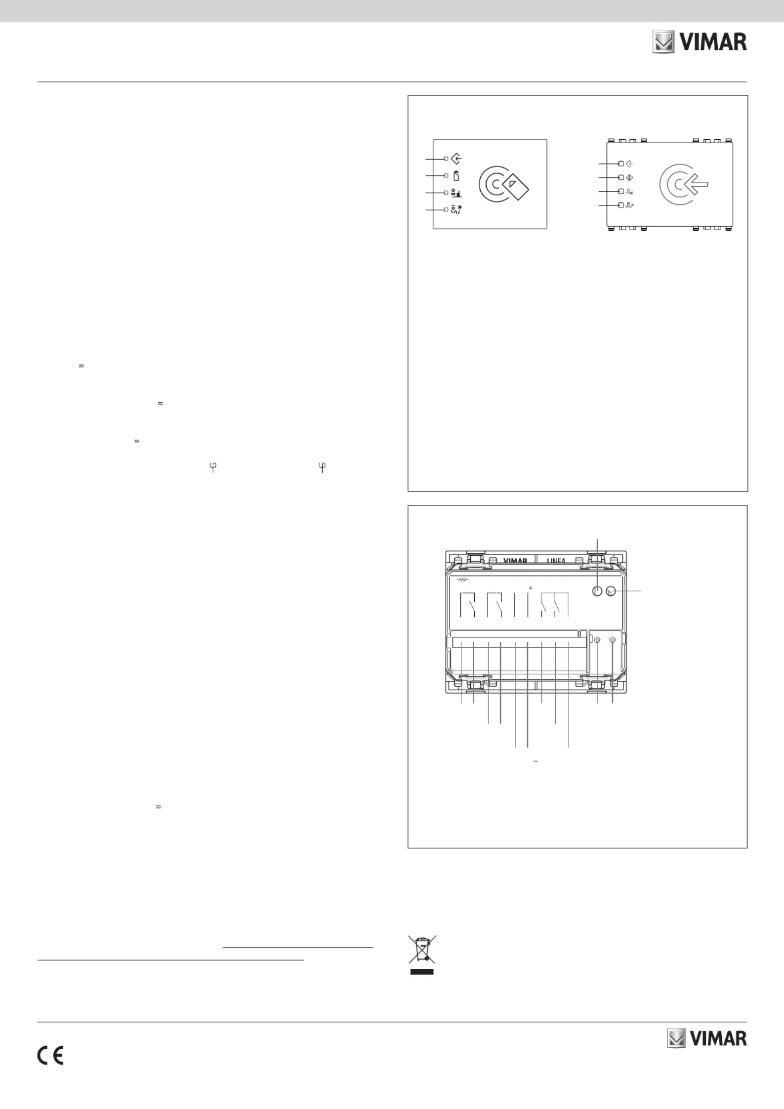
• PULSANTE configurazione: tasto per la commutazione tra modo normale o modo
programmazione o rilevamento dell’indirizzo fisico.
• LED spento: segnalazione “normale funzionamento.”
• LED rosso: segnalazione “modo indirizzamento” (il led si spegne automaticamente
dopo la programmazione dell’indirizzo fisico).
- verde fisso: segnalazione “Accesso consentito” (il led rimane illuminato per circa 3 s).
- verde lampeggiante: segnalazione nel caso in cui la fascia oraria non sia valida (il led
lampeggia per circa 3 s).
- rosso fisso: segnalazione “Accesso negato” (il led rimane illuminato per circa 3 s).
- rosso lampeggiante: segnalazione nel caso in cui la data di scadenza non sia valida.
- ambra fisso: segnalazione nel caso in cui la codifica dell’impianto non sia valida.
- ambra lampeggiante: segnalazione nel caso in cui il giorno della settimana non sia valido.
- rosso/verde lampeggiante: sincronizzare l’orologio interno del dispositivo.
- rosso: segnalazione “Non disturbare”.
- rosso lampeggiante: segnalazione “Camera occupata”.
• 3: ambra - segnalazione “Chiamata cameriera”.
• 4: verde - segnalazione “Rifare camera”.
Il significato assunto dalla segnalazione dei led dipende dagli oggetti di comunicazione (quindi dalle fun-
zioni) che vengono configurati nel lettore attraverso il software ETS. Per tutte le applicazioni nelle quali il
dispositivo viene configurato con funzioni e segnalazioni dei led diverse da quelle standard, il cliente potrà
richiedere a Vimar la personalizzazione al laser dei simboli sul frontale del lettore.
Pulsante di configurazione
Vimar SpA dichiara che l’apparecchiatura radio è conforme alla direttiva 2014/53/UE. Il
testo completo della dichiarazione di conformità UE è disponibile nella scheda di prodot-
to al seguente indirizzo Internet: www.vimar.com.
Regolamento REACh (UE) n. 1907/2006 – art.33. Il prodotto potrebbe contenere tracce
RAEE - Informazione agli utilizzatori
Il simbolo del cassonetto barrato riportato sull’apparecchiatura o sulla sua confezione indica che il prodotto alla fine della
propria vita utile deve essere raccolto separatamente dagli altri rifiuti. L’utente dovrà, pertanto, conferire l’apparecchiatura
giunta a fine vita agli idonei centri comunali di raccolta differenziata dei rifiuti elettrotecnici ed elettronici. In alternativa alla
gestione autonoma, è possibile consegnare gratuitamente l’apparecchiatura che si desidera smaltire al distributore, al mo-
mento dell’acquisto di una nuova apparecchiatura di tipo equivalente. Presso i distributori di prodotti elettronici con superfi-
cie di vendita di almeno 400 m
è inoltre possibile consegnare gratuitamente, senza obbligo di acquisto, i prodotti elettronici
da smaltire con dimensioni inferiori a 25 cm. L’adeguata raccolta differenziata per l’avvio successivo dell’apparecchiatura
dismessa al riciclaggio, al trattamento e allo smaltimento ambientalmente compatibile contribuisce ad evitare possibili ef-
fetti negativi sull’ambiente e sulla salute e favorisce il reimpiego e/o riciclo dei materiali di cui è composta l’apparecchiatura.
EIKON - ARKÉ - IDEA - PLANA