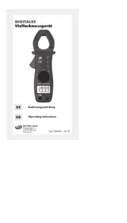
Voltcraft VC290 Manual


Læs nedenfor 📖 manual på dansk for Voltcraft VC290 (102 sider) i kategorien Multimeter. Denne guide var nyttig for 37 personer og blev bedømt med 4.7 stjerner i gennemsnit af 19 brugere

Side 1/102
°
Digital-Multimeter
BEDIENUNGSANLEITUNG Seite 4 - 27
Digital Multimeter
OPERATING INSTRUCTIONS Page 28 - 51
Multimètre numérique
NOTICE D’EMPLOI Page 52 - 75
Digitale multimeter
GEBRUIKSAANWIJZING Pagina 76 - 99
Best.-Nr. / Item-No. /
N° de commande / Bestnr.:
124501 VC250
124502 VC270
124503 VC290
Version 06/14
2
Diese Bedienungsanleitung gehört zu diesem Produkt. Sie enthält wichtige Hinweise zur Inbe-
triebnahme und Hand habung. Achten Sie hierauf, auch wenn Sie dieses Produkt an Dritte wei-
tergeben.
Heben Sie deshalb diese Bedienungsanleitung zum Nach lesen auf!
Eine Auflistung der Inhalte finden Sie in dem Inhaltsverzeichnis mit Angabe der entsprechen-
den Seitenzahlen auf Seite 5.
These operating instructions belong with this product. They contain important information for
putting it into service and operating it. This should be noted also when this product is passed on
to a third party.
Therefore look after these operating instructions for future reference!
A list of contents with the corresponding page numbers can be found in the index on page 29.
Ce mode d'emploi appartient à ce produit. Il contient des recommandations en ce qui concerne
sa mise en service et sa manutention. Veuillez en tenir compte et ceci également lorsque vous
remettez le produit à des tiers.
Conservez ce mode d'emploi afin de pouvoir vous documenter en temps utile.!
Vous trouverez le récapitulatif des indications du contenu à la table des matières avec mention
de la page correspondante à la page 53.
Deze gebruiksaanwijzing hoort bij dit product. Er staan belangrijke aanwijzingen in betreffende
de ingebruikname en gebruik, ook als u dit product doorgeeft aan derden.
Bewaar deze handleiding zorgvuldig, zodat u deze later nog eens kunt nalezen!
U vindt een opsomming van de inhoud in de inhoudsopgave met aanduiding van de pagina-
nummers op pagina 77.
3
4
Einführung
Sehr geehrter Kunde,
mit diesem Voltcraft®-Produkt haben Sie eine sehr gute Entscheidung getroffen, für die wir
Ihnen danken möchten.
Sie haben ein überdurchschnittliches Qualitätsprodukt aus einer Marken-Familie erworben, die sich
auf dem Gebiet der Mess-, Lade- und Netztechnik durch besondere Kompetenz und permanente
Innovation auszeichnet.
Mit Voltcraft® werden Sie als anspruchsvoller Bastler ebenso wie als professioneller Anwender auch
schwierigen Aufgaben gerecht. Voltcraf bietet Ihnen zuverlässige Technologie zu einem außerge-
wöhnlich günstigen Preis-Leistungs-Verhältnis.
Wir sind uns sicher: Ihr Start mit Voltcraft ist zugleich der Beginn einer langen und guten Zusammen-
arbeit.
Viel Spaß mit Ihrem neuen Voltcraft®-Produkt!
Bei technischen Fragen wenden Sie sich bitte an:
Deutschland: Tel.-Nr.: 0 96 04 / 40 87 87
Fax-Nr.: 0180 5 / 31 21 10 (der Anruf kostet 14 ct/min inkl. MwSt. aus dem Festnetz.
Mobilfunkhöchstpreis: 42 ct/min inkl. MwSt.)
E-Mail: Bitte verwenden Sie unser Formular im Internet www.conrad.de,
unter der Rubrik „Kontakt“.
Mo. - Fr. 10.00 bis 16.00 Uhr
Österreich: www.conrad.at
www.business.conrad.at
Schweiz: Tel.-Nr.: 0848/80 12 88
Fax-Nr.: 0848/80 12 89
E-Mail: support@conrad.ch
Mo. - Fr. 8.00 bis 12.00 Uhr, 13.00 bis 17.00 Uhr
5
Inhaltsverzeichnis
Einführung ............................................................................................................................................4
Bestimmungsgemäße Verwendung ......................................................................................................6
Bedienelemente ....................................................................................................................................7
Sicherheitshinweise ..............................................................................................................................8
Produktbeschreibung ..........................................................................................................................10
Lieferumfang........................................................................................................................................11
Display-Angaben und Symbole ..........................................................................................................12
Messbetrieb ........................................................................................................................................13
a) Messgerät einschalten ..........................................................................................................13
b) Spannungsmessung „V“ ........................................................................................................14
c) Strommessung „A“ ................................................................................................................14
d) Frequenzmessung (nur VC270 und VC290)..........................................................................16
e) Widerstandsmessung ............................................................................................................16
f) Diodentest..............................................................................................................................17
g) Durchgangsprüfung................................................................................................................17
h) Kapazitätsmessung (nur VC270 und VC290 ........................................................................18
i) Batterietest (nur VC250) ........................................................................................................18
REL-Funktion (nur VC270 und VC290) ......................................................................................19
HOLD-Funktion (nur VC290) ......................................................................................................19
Low Imp. 400 k -Funktion (nur VC250 und VC270) ................................................................19Ω
Auto-Power-Off-Funktion (nur VC270 und VC290) ....................................................................19
Reinigung und Wartung ......................................................................................................................20
Allgemein ....................................................................................................................................20
Reinigung ....................................................................................................................................20
Messgerät öffnen ........................................................................................................................20
Sicherungswechsel......................................................................................................................21
Einsetzen und wechseln der Batterie (nur VC250 und VC270) ..................................................22
VC290 aufladen ..........................................................................................................................22
Entsorgung ..........................................................................................................................................23
a) Produkt....................................................................................................................................23
b) Batterien/Akkus ......................................................................................................................23
Behebung von Störungen....................................................................................................................24
Technische Daten................................................................................................................................24
6
Bestimmungsgemäße Verwendung
- Messen und Anzeigen der elektrischen Größen im Bereich der Überspannungskategorie CAT III
(bis max. 600V gegen Erdpotential, gemäß EN 61010-1) und allen niedrigeren Kategorien.
- Messen von Gleich- und Wechselspannungen bis max. 600 V
- Messen von Gleich- und Wechselstrom bis max. 10 A
- Frequenzmessung bis 10 MHz (nur VC270 und VC290)
- Messen von Kapazitäten bis 100 µF (nur VC270 und VC290)
- Messen von Widerständen bis 40 M (VC250 max. 20 M )Ω Ω
- Batterietest für 1,5 und 9V-Batterien (nur VC250)
- Durchgangsprüfung (<10 akustisch)Ω
- Diodentest
Die Messfunktionen werden über den Drehschalter angewählt. Bei VC250 erfolgt die Messbereichs-
wahl manuell, bei VC270 und VC290 ist in allen Messbereichen (außer Strommessbereiche) die auto-
matische Messbereichswahl aktiv.
Die beiden Strom-Messeingänge sind gegen Überlast abgesichert. Die Spannung im Strommesskreis
darf 600 V nicht überschreiten. Die beiden Strommessbereiche sind mit keramischen Hochleistungssi-
cherungen abgesichert. Bei VC270 ist der mA/µA-Messbereich mit einer selbstrückstellenden PTC-
Sicherung ausgestattet.
Eine Niedrig-Impedanz-Funktion (Low-Imp) bei VC250 und VC270, ermöglicht die Messung mit redu-
ziertem Innenwiderstand. Dies unterdrückt Phantomspannungen die in hochohmigen Messungen auf-
treten nnen. Die Messung mit reduzierter Impedanz ist nur in Messkreisen bis max. 250 V und für
max. 3 s zulässig.
VC250 und VC270 werden mit einer handelsüblichen, 9V-Alkali-Blockbatterie betrieben. Der Betrieb
ist nur mit dem angegebenen Batterietyp zulässig. Bei VC290 übernimmt die Spannungsversorgung
ein eingebauter, hochkapazitiver Kondensator. Die Ladung erfolgt einfach an einer Netzspannungs-
quelle von 230 V/AC. Im Messbetrieb wird bei ausreichenden Lichtverhältnissen (Halogen-/Tages-
oder Sonnenlicht) der Kondensator über eine eingebaute Solarzelle gepuffert und die Betriebszeit pro
Ladung verlängert.
Das Messgerät darf im geöffneten Zustand, mit geöffnetem Batteriefach oder fehlendem Batteriefach-
deckel nicht betrieben werden. Messungen in Feuchträumen bzw. unter widrigen Umgebungsbedin-
gungen sind nicht zulässig. Widrige Umgebungsbedingungen sind:
- Nässe oder hohe Luftfeuchtigkeit,
- Staub und brennbare Gase, Dämpfe oder Lösungsmittel,
- Gewitter bzw. Gewitterbedingungen wie starke elektrostatische Felder usw.
Verwenden Sie zum Messen nur Messleitungen bzw. Messzubehör, welche auf die Spezifikationen
des Multimeters abgestimmt sind.
Eine andere Verwendung als zuvor beschrieben, führt zur Beschädigung dieses Produktes, außerdem
ist dies mit Gefahren wie z.B. Kurzschluss, Brand, elektrischer Schlag etc. verbunden. Das gesamte
Produkt darf nicht geändert bzw. umgebaut werden!
Lesen Sie die Bedienungsanleitung sorgfältig durch, und bewahren Sie diese für späteres Nachschla-
gen auf.
Die Sicherheitshinweise sind unbedingt zu beachten!
7
Bedienelemente
(Siehe Ausklappseite)
1 Angespritzter Gummischutz
2 Display mit Anschlusserklärung
3 Betriebsschalter bei VC250
REL-Taste bei VC270/VC290
4 Drehschalter
5 mAµA-Messbuchse
6 10 A-Messbuchse
7 VΩ-Messbuchse (bei Gleichgrößen „Plus“)
8 COM-Messbuchse (Bezugspotential, „Minus“)
9 Funktionstaste:
SELECT-Taste zur Funktionsumschaltung bei VC270
Hold-Taste zum Festhalten des Messwertes bei VC290
10 Low Imp. 400 k -Taste zur Impedanzumschaltung bei VC250 und VC270Ω
SELECT-Taste zur Funktionsumschaltung bei VC290
11 Solarzelle zur Pufferung des eingebauten Kondensators (nur VC290)
12 Blindabdeckung, ohne Funktion.
13 Stativ-Anschlussgewinde
14 Batteriefachschraube
15 Klappbarer Aufstellbügel
16 Batteriefach (nur VC250 und VC270)
17 Batterie- und Sicherungsfach
18 Stromsicherung F2 (bei VC270 selbstrücksetzend)
19 Stromsicherung F1
Messgebergruppen, die zur Messung am STROMNETZ verwendet werden sollen, müs-
sen entsprechend der MESSKATEGORIE III ODER IV gemäß IEC/EN 61010-031 AUS-
GELEGT werden und eine NENNSPANNUNG aufweisen, die mindestens der Spannung
des zu messenden Stromkreises entspricht.
8
Sicherheitshinweise
Lesen Sie bitte vor Inbetriebnahme die komplette Anleitung durch, sie enthält wich-
tige Hinweise zum korrekten Betrieb.
Bei Schäden, die durch Nichtbeachten dieser Bedienungsanleitung verursacht
werden, erlischt die Garantie/Gewährleistung! Für Folgeschäden übernehmen wir
keine Haftung!
Bei Sach- oder Personenschäden, die durch unsachgemäße Handhabung oder
Nichtbeachten der Sicherheitshinweise verursacht werden, übernehmen wir keine
Haftung! In solchen Fällen erlischt die Garantie/Gewährleistung.
Dieses Gerät hat das Werk in sicherheitstechnisch einwandfreien Zustand verlassen.
Um diesen Zustand zu erhalten und einen gefahrlosen Betrieb sicherzustellen, muss der Anwender
die Sicherheitshinweise und Warnvermerke beachten, die in dieser Gebrauchsanweisung enthalten
sind.
Folgende Symbole gilt es zu beachten:
Ein in einem Dreieck befindliches Ausrufezeichen weist auf wichtige Hinweise in dieser
Bedienungsanleitung hin, die unbedingt zu beachten sind.
Ein Blitzsymbol im Dreieck warnt vor einem elektrischen Schlag oder der Beeinträchti-
gung der elektrischen Sicherheit des Geräts.
Das „Pfeil“-Symbol ist zu finden, wenn Ihnen besondere Tipps und Hinweise zur Bedienung
gegeben werden sollen.
Dieses Gerät ist CE-konform und erfüllt die erforderlichen europäischen Richtlinien
Schutzklasse 2 (doppelte oder verstärkte Isolierung)
CAT II
Überspannungskategorie II für Messungen an elektrischen und elektronischen Gerä-
ten, welche über einen Netzstecker mit Spannung versorgt werden. Diese Kategorie
umfasst auch alle kleineren Kategorien (z.B. CAT I zur Messung von Signal- und Steu-
erspannungen).
CAT III Überspannungskategorie III für Messungen in der Gebäudeinstallation (z.B. Steckdosen
oder Unterverteilungen). Diese Kategorie umfasst auch alle kleineren Kategorien (z.B.
CAT II zur Messung an Elektrogeräten).
Erdpotential
Aus Sicherheits- und Zulassungsgründen (CE) ist das eigenmächtige Umbauen und/oder Verändern
des Gerätes nicht gestattet.
°
9
Wenden Sie sich an eine Fachkraft, wenn Sie Zweifel über die Arbeitsweise, die Sicherheit oder den
Anschluss des Gerätes haben.
Messgeräte und Zubehör sind kein Spielzeug und gehören nicht in Kinderhände!
In gewerblichen Einrichtungen sind die Unfallverhütungsvorschriften des Verbandes der gewerblichen
Berufsgenossenschaften für elektrische Anlagen und Betriebsmittel zu beachten.
In Schulen und Ausbildungseinrichtungen, Hobby- und Selbsthilfewerkstätten ist der Umgang mit
Messgeräten durch geschultes Personal verantwortlich zu überwachen.
Stellen Sie vor jeder Spannungsmessung sicher, dass sich das Messgerät nicht im Strommessbereich
befindet.
Die Spannung zwischen den Anschlusspunkten des Messgeräts und Erdpotential darf 600 V DC/AC in
CAT III nicht überschreiten.
Vor jedem Wechsel des Messbereiches sind die Messspitzen vom Messobjekt zu entfernen.
Seien Sie besonders Vorsichtig beim Umgang mit Spannungen >25 V Wechsel- (AC) bzw. >35 V
Gleichspannung (DC)! Bereits bei diesen Spannungen können Sie bei Berührung elektrischer Leiter
einen lebensgefährlichen elektrischen Schlag erhalten.
Überprüfen Sie vor jeder Messung Ihr Messgerät und deren Messleitungen auf Beschädigung(en).
Führen Sie auf keinen Fall Messungen durch, wenn die schützende Isolierung beschädigt (eingeris-
sen, abgerissen usw.) ist.
Um einen elektrischen Schlag zu vermeiden, achten Sie darauf, dass Sie die zu messenden Anschlüs-
se/Messpunkte während der Messung nicht, auch nicht indirekt, berühren. Über die fühlbaren Griffbe-
reichsmarkierungen an den Messspitzen darf während des Messens nicht gegriffen werden.
Verwenden Sie das Multimeter nicht kurz vor, während oder kurz nach einem Gewitter (Blitzschlag! /
energiereiche Überspannungen!). Achten Sie darauf, dass ihre Hände, Schuhe, Kleidung, der Boden,
Schaltungen und Schaltungsteile usw. unbedingt trocken sind.
Vermeiden Sie den Betrieb in unmittelbarer Nähe von:
- starken magnetischen oder elektromagnetischen Feldern
- Sendeantennen oder HF-Generatoren.
Dadurch kann der Messwert verfälscht werden.
Wenn anzunehmen ist, dass ein gefahrloser Betrieb nicht mehr möglich ist, so ist das Gerät außer
Betrieb zu setzen und gegen unbeabsichtigten Betrieb zu sichern. Es ist anzunehmen, dass ein
gefahrloser Betrieb nicht mehr möglich ist, wenn:
- das Gerät sichtbare Beschädigungen aufweist,
- das Gerät nicht mehr arbeitet und
- nach längerer Lagerung unter ungünstigen Verhältnissen oder
- nach schweren Transportbeanspruchungen.
Schalten Sie das Messgerät niemals gleich dann ein, wenn dieses von einem kalten in einen warmen
Raum gebracht wird. Das dabei entstandene Kondenswasser kann unter Umständen Ihr Gerät zerstö-
ren. Lassen Sie das Gerät uneingeschaltet auf Zimmertemperatur kommen.
11
Display (2)
Die Messgeräte der VC200-Serie unterscheiden sich in den Messfunktionen und auch im Display. Die
folgende Abbildung soll Ihnen einen Überblich über die möglichen Anzeigeelemente für Ihr DMM
geben.
Lieferumfang
Multimeter mit angespritztem Gummischutz
9V Block-Batterie (nicht bei VC290)
Sicherheitsmessleitungen
Bedienungsanleitung
12
Display-Angaben und Symbole
Die Symbole und Angaben sind je nach Modell unterschiedlich vorhanden. Dies ist eine Aufstellung
aller möglichen Symbole und Angaben der Serie VC200.
Delta-Symbol für Relativwertmessung (=Bezugswertmessung)
Autorange/AUTO steht für „Automatische Messbereichswahl“
Connect terminal Grafischer Hinweis für die Wahl der erforderlichen Messbuchsen
H Data-Hold-Funktion ist aktiv
OL oder 1. Overload = Überlauf; der Messbereich wurde überschritten
Symbol für Betriebsschalter. In gedrückter Position ist eingeschaltet.
Batteriewechselsymbol; bitte schnellstmöglich die Batterie wechseln um Mess-
fehler zu vermeiden!
Symbol für den Diodentest
Symbol für den akustischen Durchgangsprüfer
AC Wechselgröße für Spannung und Strom
DC Gleichgröße für Spannung und Strom
mV Milli-Volt (exp.–3)
V Volt (Einheit der elektrischen Spannung)
A Ampere (Einheit der elektrischen Stromstärke)
mA Milli-Ampere (exp.–3)
µA Micro-Ampere (exp.–6)
Hz Hertz (Einheit der Frequenz)
kHz Kilo-Hertz (exp.3)
MHz Mega-Hertz (exp.6)
ΩOhm (Einheit des elektrischen Widerstandes)
k Kilo-Ohm (exp.3)Ω
M Mega-Ohm (exp.6)Ω
nF Nano-Farad (exp.9; Einheit der elektrischen Kapazität, Symbol )
µF Mikro-Farad (exp.–6)
Symbol für den Batterietest
Symbol Blitz erscheint im Spannungs-Messbereich 600 V
13
Messbetrieb
Überschreiten Sie auf keinen Fall die max. zulässigen Eingangsgrößen. Berühren
Sie keine Schaltungen oder Schaltungsteile, wenn darin höhere Spannungen als 25
V ACrms oder 35 V DC anliegen können! Lebensgefahr!
Kontrollieren Sie vor Messbeginn die angeschlossenen Messleitungen auf Beschä-
digungen wie z.B. Schnitte, Risse oder Quetschungen. Defekte Messleitungen dür-
fen nicht mehr benutzt werden! Lebensgefahr!
Über die fühlbaren Griffbereichsmarkierungen an den Messspitzen darf während
des Messens nicht gegriffen werden.
Der Messbetrieb ist nur bei geschlossenem Batterie- und Sicherungsfach möglich.
Bei geöffnetem Fach sind alle Messbuchsen mechanisch gegen einstecken gesi-
chert.
Es rfen immer nur die zwei Messleitungen am Messgerät angeschlossen sein,
welche zum Messbetrieb benötigt werden. Entfernen Sie aus Sicherheitsgründen
alle nicht benötigten Messleitungen vom Messgerät.
Für jede Messfunktion wird bei VC250 und VC270 die entspre-
chende Anschlussfolge der Messbuchsen im Display angezeigt.
Beachten Sie diese beim Anschluss der Messleitungen am Mess-
gerät.
Sobald „OL“ (für Overload = Überlauf) im Display erscheint, haben
Sie den Messbereich überschritten.
a) Messgerät einschalten
Die Messgeräte der VC200 Serie werden unterschiedlich eingeschaltet.
Schalten Sie das Messgerät bei Nichtgebrauch immer aus.
VC250: Schalten Sie das Gerät durch Drücken des Betriebsschalters (3) ein. Der Schalter muss ein-
rasten. In gedrückter Position ist das Messgerät eingeschaltet. Zum Ausschalten drücken Sie
den Schalter erneut.
VC270 Drehen Sie den Drehschalter (4) in die entsprechende Messfunktion. Zum Ausschalten brin-
gen Sie den Drehschalter in Position „OFF“.
VC290 Drehen Sie den Drehschalter (4) in die entsprechende Messfunktion. Zum Ausschalten brin-
gen Sie den Drehschalter in Position „OFF“. Diese ist bei VC290 an beiden Seiten des Dreh-
bereichs vorhanden.
Bevor Sie mit dem Messgerät arbeiten können, muss erst die beiliegende Batterie einge-
setzt bzw. bei VC290 der eingebaute Kondensator geladen werden.
Das Einsetzen und Wechseln der Batterie sowie das Laden des Kondensators ist im
Kapitel „Reinigung und Wartung“ beschrieben.
15
Der µA/mA-Messeingang von VC270 weist eine selbstrückstellende PTC-Sicherung auf, bei dem ein
Sicherungswechsel bei Überlast entfällt.
Wurde die PTC-Sicherung ausgelöst (kein Messwertänderung etc.), so schalten Sie das
DMM aus (OFF) und warten ca. 5 Minuten. Die selbstrückstellende Sicherung kühlt ab
und ist danach wieder funktionsbereit.
Zur Messung von Gleichströmen (A ) gehen Sie wie folgt vor:
- Schalten Sie das DMM ein und wählen den Messbereich „A “.
- In der Tabelle sind die unterschiedlichen Messfunktionen und die möglichen Messbereiche ersicht-
lich. Wählen Sie den Messbereich und die zugehörigen Messbuchsen.
Messfunktion VC250 VC270 VC290 Messbuchsen
µA <200 µA <4000 µA <4000 µA COM + mAµA
mA 200 µA - 199 mA 4000 µA – 399 mA 4000 µA – 399 mA COM + mAµA
A 200 mA – 10 A 400 mA – 10 A 400 mA – 10 A COM + 10A
- Stecken Sie die rote Messleitung in die mAµA- oder 10A-Messbuchse. Die schwarze Messleitungs-
tecken Sie in die COM-Messbuchse.
- Verbinden Sie die beiden Messspitzen in Reihe mit dem Messobjekt (Batterie, Schaltung usw.); die
jeweilige Polarität des Messwertes wird zusammen mit dem augenblicklichen Messwert im Display
angezeigt.
Sobald bei Gleichstrommessung ein Minus „-„ vor dem Messwert erscheint, verläuft der Strom
entgegengesetzt (oder die Messleitungen sind vertauscht).
- Entfernen Sie nach Messende die Messleitungen vom Messobjekt und schalten Sie das DMM aus.
Zur Messung von Wechselströmen (A ) gehen Sie wie zuvor beschrieben vor.
- Schalten Sie das DMM ein und wählen den Messbereich „A “. Drücken Sie bei VC270 und
VC290 die Taste „SELECT“ um in den AC-Messbereich umzuschalten. Im Display erscheint „AC“.
Eine erneute Betätigung schaltet wieder zurück usw.
- Entfernen Sie nach Messende die Messleitungen vom Messobjekt und schalten Sie das DMM aus.
Messen Sie im 10A-Bereich auf keinen Fall Ströme über 10 A bzw. im mA/µA-
Bereich Ströme über 400 mA, da sonst die Sicherungen auslösen.
16
d) Frequenzmessung (nur VC270 und VC290)
Das DMM ka
nn die Fre
quenz einer Signalspannung von 10 Hz - 10 MHz messen und anzeigen.
Zur Messung von Frequenzen gehen Sie wie folgt vor:
-
Schalten Sie das DMM ein und wählen den Messbereich „Hz“. Im Display
erscheint „Hz“.
- Stecken Sie die rote Messleitung in die Hz-Messbuchse (7), die schwarze
Messleitung in die COM-Messbuchse (8).
- Verbinden Sie die beiden Messspitzen mit dem Messobjekt (Signalgene-
rator, Schaltung usw.).
- Die Frequenz wird mit der entsprechenden Einheit im Display angezeigt.
- Entfernen Sie nach Messende die Messleitungen vom Messobjekt und
schalten Sie das DMM aus.
e) Widerstandsmessung
Vergewissern Sie sich, dass alle zu messenden Schaltungsteile, Schaltungen und
Bauelemente sowie andere Messobjekte unbedingt spannungslos und entladen
sind.
Zur Widerstandsmessung gehen Sie wie folgt vor:
- Schalten Sie das DMM ein und wählen den Messbereich “. Ω
- Stecken Sie die rote Messleitung in die -Messbuchse (7), die schwarzeΩ
Messleitung in die COM-Messbuchse (8).
- Überprüfen Sie die Messleitungen auf Durchgang, indem Sie die beiden
Messspitzen verbinden. Daraufhin muss sich ein Widerstandswert von
ca. 0 - 0,5 Ohm einstellen (Eigenwiderstand der Messleitungen).
- Bei niederohmigen Messungen drücken Sie am VC270 und VC290 die Taste „REL“ (3), um den
Eigenwiderstand der Messleitungen nicht in die folgende Widerstandsmessung einfließen zu las-
sen. Die Anzeige zeigt 0 Ohm. Die automatische Bereichswahl (Autorange) ist deaktiviert. Die Auto-
range-Funktion wird durch einen Wechsel der Messfunktion wieder aktiviert (z.B. Taste „SELECT“
2 x drücken).
- Verbinden Sie nun die beiden Messspitzen mit dem Messobjekt. Der Messwert wird, sofern das
Messobjekt nicht hochohmig oder unterbrochen ist, im Display angezeigt. Warten Sie, bis sich die
Anzeige stabilisiert hat. Bei Widerständen >1 MOhm kann dies einige Sekunden dauern.
- Sobald „OL“ (für Overload = Überlauf) im Display erscheint, haben Sie den Messbereich überschrit-
ten bzw. der Messkreis ist unterbrochen.
- Entfernen Sie nach Messende die Messleitungen vom Messobjekt und schalten Sie das DMM aus.
Wenn Sie eine Widerstandsmessung durchführen, achten Sie darauf, dass die Messpunkte,
welche Sie mit den Messspitzen zum Messen berühren, frei von Schmutz, Öl, Lötlack oder
ähnlichem sind. Solche Umstände können das Messergebnis verfälschen.
17
f) Diodentest
Vergewissern Sie sich, dass alle zu messenden Schaltungsteile, Schaltungen und
Bauelemente sowie andere Messobjekte unbedingt spannungslos und entladen
sind.
- Schalten Sie das DMM ein und wählen den Messbereich
- Drücken Sie bei VC270 und VC290 die Taste „SELECT“ um die Mess-
funktion umzuschalten. Im Display erscheint das Diodensymbol. Eine
erneute Betätigung schaltet in die nächste Messfunktion usw.
- Stecken Sie die rote Messleitung in die -Messbuchse (7), die schwar-Ω
ze Messleitung in die COM-Messbuchse (8).
- Überprüfen Sie die Messleitungen auf Durchgang, indem Sie die beiden
Messspitzen verbinden. Daraufhin muss sich ein Wert von ca. 0 V ein-
stellen.
- Verbinden Sie die beiden Messspitzen mit dem Messobjekt (Diode).
- Im Display wird die Durchlassspannung „UF“ in Volt (V) angezeigt. Ist
„OL“ ersichtlich, so wird die Diode in Sperrrichtung (UR) gemessen oder
die Diode ist defekt (Unterbrechung). Führen Sie zur Kontrolle eine
gegenpolige Messung durch.
- Entfernen Sie nach Messende die Messleitungen vom Messobjekt und schalten Sie das DMM aus.
g) Durchgangsprüfung
Vergewissern Sie sich, dass alle zu messenden Schaltungsteile, Schaltungen und
Bauelemente sowie andere Messobjekte unbedingt spannungslos und entladen
sind.
- Schalten Sie das DMM ein und wählen den Messbereich bzw.
- Drücken Sie bei VC270 und VC290 die Taste „SELECT“ 2x um die
Messfunktion umzuschalten. Im Display erscheint das Symbol für
Durchgangsprüfung. Eine erneute Betätigung schaltet in die erste
Messfunktion usw.
- Stecken Sie die rote Messleitung in die -Messbuchse (7), dieΩ
schwarze Messleitung in die COM-Messbuchse (8).
- Als Durchgang wird ein Messwert < 10 Ohm erkannt und es ertönt ein
Piepton.
- Sobald „OL“ (für Overload = Überlauf) bzw. 1 im Display erscheint,
haben Sie den Messbereich überschritten bzw. der Messkreis ist
unterbrochen.
- Entfernen Sie nach Messende die Messleitungen vom Messobjekt und schalten Sie das DMM aus.
18
h) Kapazitätsmessung (nur VC270 und VC290)
Vergewissern Sie sich, dass alle zu messenden Schaltungsteile, Schaltungen und
Bauelemente sowie andere Messobjekte unbedingt spannungslos und entladen
sind.
Beachten Sie bei Elektrolyt-Kondensatoren unbedingt die Polarität.
- Schalte
n Sie das DMM ein und wählen den Messbereich
- Stecken Sie die rote Messleitung in die V-Messbuchse (7), die schwarze
Messleitung in die COM-Messbuchse (8).
- In der Anzeige erscheint die Einheit „nF“.
Aufgrund des empfindlichen Messeingangs kann es bei „offenen“
Messleitungen zu einer Wertanzeige im Display kommen. Durch
Drücken der Taste „REL“ wird die Anzeige auf „0“ gesetzt. Die Auto-
range-Funktion bleibt aktiv.
- Verbinden Sie nun die beiden Messspitzen (rot = Pluspol/schwarz = Minuspol) mit dem Messobjekt
(Kondensator). Im Display wird nach einer kurzen Zeit die Kapazität angezeigt. Warten Sie, bis sich
die Anzeige stabilisiert hat. Bei Kapazitäten >40 µF kann dies einige Sekunden dauern.
- Sobald „OL“ (für Overload = Überlauf) im Display erscheint, haben Sie den Messbereich überschrit-
ten.
- Entfernen Sie nach Messende die Messleitungen vom
Messobjekt und schalten Sie das DMM aus.
i) Batterietest (nur VC250)
Der Batterietest dient zum schnellen Überprüfen der gängigsten 1,5 und 9V-Batterien. Für ein objekti-
ves Messergebnis werden die Batterien unter geringer Belastung gemessen. In der Anzeige erscheint
die tatsächliche Polspannung unter Belastung. Die Messung ist ebenso bei Akkus möglich. Wählen
Sie dazu den Messbereich, der Ihrem Akku am nächsten ist (z.B. Messbereich 1,5 V für 1,2 V-Akku)
- Schalten Sie das DMM ein und wählen den Messbereich
- Stecken Sie die rote Messleitung in die mA µA-Messbuchse (5), die
schwarze Messleitung in die COM-Messbuchse (8).
- In der Anzeige erscheint die Einheit „V“.
Bei Akkus ist aufgrund der geringeren Zellenspannung auch das
Messergebnis niedriger als bei normalen Batterien.
- Sobald „1.“ im Display erscheint, haben Sie den Messbereich überschrit-
ten.
- Entfernen Sie nach Messende die Messleitungen vom Messobjekt und schalten Sie das DMM aus
.
19
REL-Funktion (nur VC270 und VC290)
Die REL-Funktion ermöglicht eine Bezugswertmessung um evtl. Leitungsverluste wie z.B. bei Wider-
standsmessungen zu vermeiden. Hierzu wird der momentane Anzeigewert auf Null gesetzt. Ein neuer
Bezugswert wurde eingestellt.
Durch Drücken der „REL“-Taste wird diese Messfunktion aktiviert. Im Display erscheint “. Die
automatische Messbereichswahl wird dabei deaktiviert (außer Kapazitätsmessbereich).
Um diese Funktion abzuschalten, wechseln Sie die Messfunktion.
Die REL-Funktion ist nicht aktiv im Frequenz-Messbereich sowie im hochohmigen
Widerstandsmessbereich, bei Diodentest und Durchgangsprüfung.
HOLD-Funktion (nur VC290)
Die HOLD-Funktion friert den momentan dargestellten Messwert ein, um diesen in Ruhe abzulesen
oder zu protokollieren.
Stellen Sie bei der Überprüfung von spannungsführenden Leitern sicher, dass die-
se Funktion bei Testbeginn deaktiviert ist. Es wird sonst ein falsches Messergeb-
nis vorgetäuscht!
Zum Einschalten der Hold-Funktion drücken Sie die Taste „H“ (9); ein Signalton bestätigt diese Aktion
und es wird „H“ im Display angezeigt.
Um die HOLD-Funktion abzuschalten, drücken Sie die Taste „H“ (9) erneut oder wechseln Sie die
Messfunktion.
Low Imp. 400 k -Funktion (nur VC250 und VC270)
Ω
Ω
Ω
ΩΩ
Diese Funktion darf nur bei Spannungen bis max. 250 V und nur bis max. 3 Sekun-
den verwendet werden!
Diese Messfunktion ermöglicht die Herabsetzung der Messimpedanz von 10 M auf 400 k . DurchΩ Ω
das Senken der Messimpedanz werden mögliche Phantomspannungen unterdrückt, die das Messer-
gebnis verfälschen könnten.
Drücken Sie diese Taste während der Spannungsmessung (max. 250 V!) für max. 3 Sekunden. Nach
dem loslassen hat das Multimeter wieder die normale Messimpedanz von 10 M .Ω
Auto-Power-Off-Funktion (nur VC270 und VC290)
Das DMM schaltet nach 30 Minuten automatisch ab, wenn keine Taste oder der Drehschalter betätigt
wurde. Diese Funktion schützt und schont die Batterie und verlängert die Betriebszeit.
Um das DMM nach einer automatischen Abschaltung wieder einzuschalten betätigen Sie den Dreh-
schalter oder drücken die „REL“ oder „SELECT“-Taste.
20
Die Auto-Power-Off-Funktion kann manuell abgeschaltet werden.
Schalten Sie dazu das Messgerät aus (OFF). Halten Sie die Taste „SELECT“ gedrückt und schalten
das DMM am Drehschalter ein. Die Funktion ist solange inaktiv, bis das Messgerät über den Dreh-
schalter ausgeschaltet wird.
Reinigung und Wartung
Allgemein
Um die Genauigkeit des Multimeters über einen längeren Zeitraum zu gewährleisten, sollte es jährlich
einmal kalibriert werden.
Das Messgerät ist bis auf eine gelegentliche Reinigung und den Sicherungswechsel absolut war-
tungsfrei.
Den Sicherungs- und Batteriewechsel finden Sie im Anschluss.
Überprüfen Sie regelmäßig die technische Sicherheit des Gerätes und der Messlei-
tungen z.B. auf Beschädigung des Gehäuses oder Quetschung usw.
Reinigung
Bevor Sie das Gerät reinigen beachten Sie unbedingt folgende Sicherheitshinweise:
Beim Öffnen von Abdeckungen oder Entfernen von Teilen, außer wenn dies von
Hand möglich ist, können spannungsführende Teile freigelegt werden.
Vor einer Reinigung oder Instandsetzung müssen die angeschlossenen Leitungen vom Messgerät
und von allen Messobjekten getrennt werden. Schalten Sie das DMM aus.
Verwenden Sie zur Reinigung keine carbonhaltigen Reinigungsmittel, Benzine, Alkohole oder ähnli-
ches. Dadurch wird die Oberfläche des Messgerätes angegriffen. Außerdem sind die Dämpfe gesund-
heitsschädlich und explosiv. Verwenden Sie zur Reinigung auch keine scharfkantigen Werkzeuge,
Schraubendreher oder Metallbürsten o.ä.
Zur Reinigung des Gerätes bzw. des Displays und der Messleitungen nehmen Sie ein sauberes, fus-
selfreies, antistatisches und leicht feuchtes Reinigungstuch. Lassen Sie das Gerät komplett abtrock-
nen, bevor Sie es für den nächsten Messeinsatz verwenden.
Messgerät öffnen
Ein Sicherungs-. und Batteriewechsel ist aus Sicherheitsgründen nur glich, wenn alle Messleitun-
gen vom Messgerät entfernt wurden. Das Batterie- und Sicherungsfach (17) lässt sich bei eingesteck-
ten Messleitungen nicht öffnen.
Zusätzlich werden beim Öffnen alle Messbuchsen mechanisch verriegelt, um das nachträgliche Ein-
stecken der Messleitungen bei geöffnetem Gehäuse zu verhindern. Die Verriegelung wird automatisch
aufgehoben, wenn das Batterie- und Sicherungsfach wieder verschlossen ist.
21
Das Gehäusedesign lässt selbst bei geöffnetem Batterie- und Sicherungsfach
nur den Zugriff auf Batterie und Sicherungen zu. Das Gehäuse muss nicht
mehr wie üblich komplett geöffnet und zerlegt werden.
Diese Maßnahmen erhöhen die Sicherheit und Bedienungsfreundlichkeit für
den Anwender.
Zum Öffnen gehen Sie wie folgt vor:
- Entfernen Sie alle Messleitungen vom Messgerät und schalten es aus.
- Lösen und entfernen Sie die rückseitige Batteriefachschraube (14).
- Ziehen Sie bei zugeklapptem Aufstellbügel das Batterie- und Sicherungs-
fach (17) nach unten vom Messgerät.
- Die Sicherungen und das Batteriefach sind jetzt zugänglich.
- Verschließen Sie das Gehäuse in umgekehrter Reihenfolge und verschrau-
ben Sie das Batterie- und Sicherungsfach.
- Das Messgerät ist wieder einsatzbereit.
Sicherungswechsel
Die Strommessbereiche sind mit Hochleistungssicherungen abgesichert. Ist keine Messung in diesem
Bereich mehr möglich, muss die Sicherung ausgewechselt werden.
Zum Auswechseln gehen Sie wie folgt vor:
- Trennen Sie die angeschlossenen Messleitungen vom Messkreis und von Ihrem Messgerät. Schal-
ten Sie das DMM aus.
- Öffnen Sie das Gehäuse wie im Kapitel „Messgerät öffnen“ beschrieben.
- Ersetzen Sie die defekte Sicherung gegen eine neue des selben Typs und Nennstromstärke. Die
Sicherungen haben folgende Werte:
Sicherung F1 F2
VC250 F10A 600V (6,35 x 31,8 mm) FF 200 mA 600V (32 x 6 mm)
VC270 F10A 600V (6,35 x 31,8 mm) 3 x F 160 mA/600 V selbstrückstellend,
PTC (32 x 6,2 mm)
VC290 F10A 600V (6,35 x 31,8 mm) FF 400 mA 600V (6,35 x 31,8 mm)
Schaltvermögen 10 kA
- Verschließen Sie das Gehäuse wieder sorgfältig.
Die Verwendung geflickter Sicherungen oder das Überbrücken des Sicherungshal-
ters ist aus Sicherheitsgründen nicht zulässig. Dies kann zum Brand oder zur
Lichtbogenexplosion führen. Betreiben Sie das Messgerät auf keinen Fall im geöff-
neten Zustand.
22
Einsetzen und wechseln der Batterie (nur VC250 und VC270)
Zum Betrieb des Messgerätes wird eine 9V-Blockbatterien (z.B. 1604A) benötigt. Bei Erstinbetrieb-
nahme oder wenn das Batterie-Wechselsymbol bzw. im Display erscheint, muss eine neue,
volle Batterie eingesetzt werden.
Zum Einsetzen/Wechseln gehen Sie wie folgt vor:
- Trennen Sie die angeschlossenen Messleitungen vom Messkreis und von Ihrem Messgerät. Schal-
ten Sie das DMM aus.
- Öffnen Sie das Gehäuse wie im Kapitel „Messgerät öffnen“ beschrieben.
- Ersetzen Sie die verbrauchte Batterie gegen eine neue des selben Typs. Setzen Sie die neue Bat-
terie polungsrichtig in das Batteriefach (16). Achten Sie auf die Polaritätsangaben im Batteriefach.
- Verschließen Sie das Gehäuse wieder sorgfältig.
Betreiben Sie das Messgerät auf keinen Fall im geöffneten Zustand.
!LEBENSGEFAHR!
Lassen Sie keine verbrauchten Batterien im Messgerät, da selbst auslaufgeschütz-
te Batterien korrodieren können und dadurch Chemikalien freigesetzt werden kön-
nen, welche Ihrer Gesundheit schaden bzw. das Gerät zerstören.
Lassen Sie keine Batterien achtlos herumliegen. Diese könnten von Kindern oder
Haustieren verschluckt werden. Suchen Sie im Falle eines Verschluckens sofort
einen Arzt auf.
Entfernen Sie die Batterien bei längerer Nichtbenutzung aus dem Gerät, um ein
Auslaufen zu verhindern.
Ausgelaufene oder beschädigte Batterien können bei Berührung mit der Haut Ver-
ätzungen verursachen. Benutzen Sie deshalb in diesem Fall geeignete Schutz-
handschuhe.
Achten Sie darauf, dass Batterien nicht kurzgeschlossen werden. Werfen Sie keine
Batterien ins Feuer.
Batterien rfen nicht aufgeladen oder zerlegt werden. Es besteht Explosionsge-
f
ahr.
Eine passende Alkaline Batterie erhalten Sie unter folgender Bestellnummer:
Best.-Nr. 65 25 09 (Bitte 1x bestellen).
Verwenden Sie nur Alkaline Batterien, da diese leistungsstark und langlebig sind.
VC290 aufladen
Da
s VC290 kommt ganz ohne Batterien aus. Die Spannungsversorgung übernimmt ein integrierter,
hochkapazitiver Kondensator (High-Cap). Dieser Kondensator kann über eine Ladefunktion am Dreh-
schalter an jeder Wechselspannungsquelle von 230 V/AC (Netzspannung) aufgeladen werden.
Eine Solarzelle (11) puffert bei ausreichenden Lichtverhältnissen unabhängig von der Messfunktion den
Ladekondensator und verlängert so zusätzlich die Betriebszeit.
23
Zum Laden an Netzspannung (230 V/AC) gehen Sie wie folgt vor:
- Schalten Sie das DMM ein und wählen den Bereich „CHARGE“.
- Stecken Sie die rote Messleitung in die V-Messbuchse (7), die schwarze
Messleitung in die COM-Messbuchse (8).
- In der Anzeige erscheint das Symbol „CHARGE!und die relative Lade-
spannung. Diese reicht von 2,600 V (Leer) bis ca.3,999 V. Ist der High-
Cap geladen, so wird im Display „OL“ angezeigt. Eine Ladung von ca.
10 Minuten reicht im DC-V-Messbereich für ca. 180 Minuten Messzeit.
- Wurde der High-Cap völlig entladen und es erscheint keine Anzeige, drü-
cken Sie während des Ladebetriebs die Taste „RESET“ (3). Das DMM
wird reaktiviert.
Entsorgung
a) Produkt
Elektronische Geräte sind Wertstoffe und gehören nicht in den Hausmüll.
Entsorgen Sie das Produkt am Ende seiner Lebensdauer gemäß den geltenden gesetzli-
chen Bestimmungen.
Entnehmen Sie evtl. eingelegte Batterien/Akkus und entsorgen Sie diese getrennt vom
Produkt.
b) Batterien/Akkus
Sie als Endverbraucher sind gesetzlich (Batterieverordnung) zur Rückgabe aller gebrauchten Batte-
rien/Akkus verpflichtet; eine Entsorgung über den Hausmüll ist untersagt.
Schadstoffhaltige Batterien/Akkus sind mit dem nebenstehenden Symbol gekennzeich-
net, das auf das Verbot der Entsorgung über den Hausmüll hinweist. Die Bezeichnung für
das ausschlaggebende Schwermetall sind: Cd=Cadmium, Hg=Quecksilber, Pb=Blei (Die
Bezeichnung steht auf den Batterien/Akkus z.B. unter dem links abgebildeten Müllton-
nen-Symbol).
Ihre verbrauchten Batterien/Akkus können Sie unentgeltlich bei den Sammelstellen Ihrer
Gemeinde, unseren Filialen oder überall dort abgeben, wo Batterien/Akkus verkauft wer-
den.
Sie erfüllen damit die gesetzlichen Verpflichtungen und leisten Ihren Beitrag zum Umweltschutz.
25
Gleichspannung
Bereich
Genauigkeit Aufsung Bereich Genauigkeit Auflösung
VC250 VC270/290 VC270 VC290
200 mV 0,1 mV 400 mV ±(0,8% + 10) ±(0,8% + 10) 0,1 mV
2 V ±(0,5% + 8) 1 mV 4 V 1 mV
20 V 0,01 V 40 V ±(0,8% + 10) ±(0,8% + 10) 0,01 V
200 V 0,1 V 400 V 0,1 V
600 V ±(0,8% + 8) 1 V 600 V ±(1% + 10) ±(1% + 10) 1 V
Überlastschutz 600 V
Wechselspannung
Bereich
Genauigkeit Aufsung Bereich Genauigkeit Auflösung
VC250 VC270/290 VC270 VC290
2 V 0,001 V 4 V 0,001 V
20 V ±(1,0% + 10) 0,01 V 40 V ±(1,3% + 7) ±(1,5% + 8) 0,01 V
200 V 0,1 V 400 V 0,1 V
600 V ±(1,3% + 7) 1 V 600 V ±(1,6% + 7) ±(1,6% + 7) 1 V
Frequenzbereich 40 – 400 Hz; Effektiver Mittelwert bei Sinus-Spannung; Überlastschutz 600 V
Gleichstrom
Bereich
Genauigkeit Aufsung Bereich Genauigkeit Auflösung
VC250 VC270/290 VC270 VC290
200 µA 0,1 µA 400 µA ±(1,3% + 2) ±(1,2% + 10) 0,1 µA
2 mA 0,001 mA 4000 µA 0,001 mA
20 mA ±(1,0% + 5) 0,01 mA 40 mA ±(1,6% + 4) ±(1,5% + 10) 0,01 mA
200 mA 0,1 mA 400 mA 0,1 mA
10 A ±(1,6% + 7) 0,01 A 4 A ±(2,0% + 10) ±(2,0% + 8) 0,001 A
10 A 0,01 A
Überlastschutz: Sicherungen; Messzeitbegrenzung >5 A: max. 10 s mit Pause von 15 min
Wechselstrom
Bereich
Genauigkeit Aufsung Bereich Genauigkeit Auflösung
VC250 VC270/290 VC270 VC290
200 µA ±(1,3% + 7) 0,1 µA 400 µA ±(1,6% + 2) ±(2,0% + 8) 0,1 µA
2 mA 0,001 mA 4000 µA 0,001 mA
20 mA 0,01 mA 40 mA ±(2,0% + 8) ±(2,6% + 7) 0,01 mA
200 mA 0,1 mA 400 mA 0,1 mA
10 A ±(2,6% + 7) 0,01 A 4 A ±(2,6% + 4) ±(3,3% + 7) 0,001 A
10 A 0,01 A
Überlastschutz: Sicherungen; Messzeitbegrenzung >5 A: max. 10 s mit Pause von 15 min
26
Widerstand
Bereich
Genauigkeit Aufsung Bereich Genauigkeit Auflösung
VC250 VC270/290 VC270 VC290
200 0,1 400 ±(1,5% + 10) ±(1,5% + 10) 0,1 Ω Ω Ω Ω
2 k 0,001 k 4 k 0,001 kΩ Ω Ω Ω
20 k ±(1,0% + 8) 0,01 k 40 k ±(1,3% + 2) ±(1,3% + 3) 0,01 kΩ Ω Ω Ω
200 k 0,1 k 400 k 0,1 kΩ Ω Ω Ω
2 M 0,001 M 4 M ±(1,5% + 10) ±(1,6% + 3) 0,001 MΩ Ω Ω Ω
20 M ±(1,6% + 7) 0,01 M 40 M ±(2,0% + 8) ±(2,0% + 5) 0,01 MΩ Ω Ω Ω
Überlastschutz 600V; Messspannung: ca. 0,45 V
Kapazität
Bereich Genauigkeit Auflösung
VC270/290 VC270 VC290
40 nF ±(3,9% + 13) ±(3,9% + 13) 0,01 nF
400 nF 0,1 nF
4 µF ±(3,9% + 7) ±(3,9% + 7) 0,001 µF
40 µF 0,01 µF
100 µF ±(5,2% + 7) ±(5,2% + 7) 0,1 µF
Überlastschutz 600V
Frequenz
Bereich Genauigkeit Auflösung
VC270/290 VC290 VC270
10 Hz – 10 MHz ±(0,1% + 5) 0,001 Hz – 0,01 MHz
Überlastschutz 600V
Empfindlichkeit1 MHz : 300 mV; Amplitude max. 30 V
Empfindlichkeit >1 MHz : 600 mV; Amplitude max. 30 V
Batterietest
Bereich VC250 Lastwiderstand Auflösung
1,5 V ca. 15 0,001 VΩ
9 V ca. 1 k 0,01 VΩ
Überlastschutz: selbstrücksetzende PTC-Sicherung
27
Diodentest
Prüfspannung Auflösung
VC250 ca. 3,0 V 0,001 V
VC270 ca. 1,48 V 0,001 V
VC290 ca. 1,48 V 0,001 V
Überlastschutz: 600 V
Akust. Durchgangsprüfer <10 W Dauerton, Überlastschutz 600 V
Überschreiten Sie auf keinen Fall die max. zulässigen Eingangsgrößen. Berühren
Sie keine Schaltungen oder Schaltungsteile, wenn darin höhere Spannungen als 25
V Acrms oder 35 V DC anliegen können! Lebensgefahr!
28
Introduction
Dear Customer,
Thank you for making the excellent decision to purchase this Voltcraft® product.
You have acquired a quality product from a brand family which has distinguished itself in the fields of
measuring, charging and network technology thanks to its particular expertise and its permanent inno-
vation.
With Voltcraft®, you will be able to cope even with difficult tasks as either an ambitious hobbyist or as
a professional user. Voltcraft® offers you reliable technology and extremely good value for money.
We are certain: Your starting to use Voltcraft will also be the beginning of a long, successful relation-
ship.
We hope you will enjoy using your new Voltcraft® product!
If there are any technical questions, contact:
Germany: Tel. no.: +49 9604 / 40 88 80
Fax. no.: +49 9604 / 40 88 48
E-mail: tkb@conrad.de
Mon. to Thur. 8.00am to 4.30pm, Fri. 8.00am to 2.00pm
29
Table of Contents
Introduction..........................................................................................................................................28
Intended Use ......................................................................................................................................30
Controls ..............................................................................................................................................31
Safety Instructions ..............................................................................................................................32
Product Description ............................................................................................................................34
Delivery Contents ................................................................................................................................35
Display Information and Symbols ........................................................................................................36
Measuring Mode..................................................................................................................................37
a) Switching on the Measuring Instrument ................................................................................37
b) Measuring Voltage “V” ..........................................................................................................38
c) Measuring Current “A” .......................................................................................................... 38
d) Measuring Frequency “ (only VC270 and VC290) ................................................................40
e) Measuring Resistance ..........................................................................................................40
f) Diode Test..............................................................................................................................41
g) Continuity Check....................................................................................................................41
h) Measuring Capacity (only VC270 and VC290) ......................................................................42
i) Battery Test “ (only VC250)....................................................................................................42
REL Function (only VC270 and VC290)......................................................................................43
HOLD Function (only VC290)......................................................................................................43
Low Imp. 400 k Function (only VC250 and VC270) ................................................................43Ω
Auto-Power-Off Function (only VC270 and VC290)....................................................................43
Cleaning and Maintenance..................................................................................................................44
General........................................................................................................................................44
Cleaning ......................................................................................................................................44
Opening the Measuring Instrument ............................................................................................44
Changing the Fuse ......................................................................................................................45
Inserting and Changing the Battery (only VC250 and VC270)....................................................46
Charging the VC290....................................................................................................................46
Disposal ..............................................................................................................................................47
a) Product....................................................................................................................................47
b) Batteries/rechargeable batteries ............................................................................................47
Troubleshooting ..................................................................................................................................48
Technical Data.................................................................................................................................... 48
30
Intended Use
- Measuring and displaying electric parameters in the range of excess voltage category CAT III (up to
max. 600V against earth potential, pursuant to EN 61010-1) and all lower categories.
- Measurement of direct and alternating voltage up to a maximum of 600V
- Measurement of direct and alternating current up to a maximum of 10 A
- Frequency measurement to 10 MHz (only VC270 and VC290)
- Capacity measurement to 100 µF (only VC270 and VC290)
- Measurement of Resistance to 40 M (VC250 max. 20 M )Ω Ω
- Battery Test for 1.5 and 9V Batteries (only VC250)
- Continuity check (< 10 acoustic)Ω
- Diode Test
The measurement functions are selected using the dial switch. With the VC250 the selection of the
measurement range is made manually, for the VC270 and VC290 the automatic measurement range
selection is active in all measurement ranges (except current measurement ranges).
The two current measuring inputs are secured against overload. The voltage in the measuring circuit
may not exceed 600 V. The two current measuring inputs are secured with ceramic high performance
fuses. The VC270 has a self-resetting PTC fuse in the mA/µA measurement range.
A low-impedance function (Low-Imp) in the VC250 and VC270 allows measurement with reduced
internal resistance. This suppresses phantom charges which can occur in high Ohm measurements.
Measurement with reduced impedance is only allowed in measurement circuits up to max. 250 V and
for a max. of 3 seconds.
VC250 and VC270 are operated with one standard 9v block battery. The device may only be operat-
ed with the specified batteries. Power for the VC290 is provided by an inbuilt high-capacity capacitor.
Charging is carried out via a mains power source 230 V/AC. During measurements, if there is sufficient
light supplied (halogen/daylight or sunlight), the capacitor is buffered by an inbuilt solar cell and the
operation time per charge is increased.
The measuring instrument must not be operated when it is open, i.e. with an open battery compart-
ment or when the battery compartment cover is missing. Measuring in damp rooms or under
unfavourable ambient conditions is not admissible. Adverse ambient conditions include:
- Excessive dampness or humidity,
- Dust or combustible gases, vapours or solvents,
- Electrical storms or stormy conditions resulting in strong electrostatic fields, etc.
For safety reasons, when measuring only use measuring cables or accessories which are adjusted to
the specifications of the multimeter.
Any use other than that described above will damage the product and may involve other risks, such as
short-circuit, fire, electric shock. Do not change or modify any part of the product.
Read the operating instructions carefully and retain them for later reference.
The safety instructions must be observed!
31
Controls
(see fold-out page)
1 Spray-on rubber protection
2 Display with connection description
3 Operation switch on VC250
REL button on VC270/VC290
4 Dial switch
5 mAµA measuring socket
6 10 A measuring socket
7 VΩmeasuring socket (“plus” when DC)
8 COM measuring socket (reference potential/ground, “minus”)
9 Function button:
SELECT button for function switching in the VC270
Hold button to hold a measured value in the VC290
10 Low Imp. 400 k buttom for impedance switching in VC250 and VC270Ω
SELECT button for function switching in the VC290
11 Solar cell for buffering inbuilt capacitor (only VC290)
12 Cover, no function.
13 Tripod connection
14 Battery compartment screw
15 Foldable setup brackets
16 Battery compartment (only VC250 and VC270)
17 Battery and fuse compartment
18 F2 current fuse (self resetting on VC270)
19 F1 current fuse
Probe assemblies to be used for MAINS measurements shall be RATED as appropriate
for MEASUREMENT CATEGORY III or IV according to IEC/EN 61010-031 and shall
have a voltage RATING of at least the voltage of the circuit to be measured.
32
Safety Instructions
Please read all of the operating instructions before using the product for the first
time; they contain important information about the correct operation.
The warranty/guarantee is rendered void in cases of damage resulting from failure
to comply with these operating instructions! We do not accept any liability for con-
sequential damages!
Nor do we assume liability for damage to property or personal injury caused by
improper use or the failure to observe the safety instructions! In such cases the
warranty/guarantee is voided.
This device left the factory in perfect condition in terms of safety engineering.
To maintain this condition and ensure safe operation, you, as the user, must comply with the safety
instructions and warnings contained in these instructions.
The following symbols must be observed:
An exclamation mark in a triangle shows important information in this user’s manual that
has to be observed.
The triangle containing a lightning symbol warns of danger of an electric shock or of the
impairment of the electrical safety of the device.
The “arrow” symbol indicates special information and advice on operation of the device.
This product has been CE-tested and meets the necessary European guidelines.
Class 2 insulation (double or reinforced insulation)
CAT II
Overvoltage category II for measurements on electric and electronic devices connected
to the mains supply with a power plug. This category also covers all smaller categories
(e.g. CAT I for measuring signal and control voltages).
CAT III Overvoltage category III for measuring in building installation (e.g. sockets or sub-distrib-
ution). This category also covers all smaller categories (e.g. CAT II for measuring elec-
tronic devices).
Earth potential
For safety and licensing reasons (CE), unauthorised conversion and/or modification of the device is
not permitted.
°
33
Consult an expert when in doubt about the operation, the safety or the connection of the device.
Measuring instruments and accessories are not toys and have no place in the hands of children!
On industrial sites the accident prevention regulations of the association of the industrial workers’ soci-
ety for electrical equipment and utilities must be followed.
In schools, training centres, computer and self-help workshops, handling of measuring instruments
must be supervised by trained personnel in a responsible manner.
Before measuring voltages, always make sure that the measuring instrument is not set to a measuring
range for electrical currents.
The voltage between the measuring instrument connection points and earth must never exceed 600 V
DC/AC in CAT III.
The test probes have to be removed from the measured object every time the measuring range is
changed.
Take particular care when dealing with voltages exceeding 25 V AC or 35 V DC! Even at these volt-
ages it is possible to get a fatal electric shock if you touch electrical conductors.
Prior to each measurement, check your instrument, including its measuring lines, for any damage.
Never carry out measurements when the protective insulation is damaged (ripped, torn off etc.).
In order to avoid an electric shock, ensure that you do not touch the connections to be measured, even
indirectly, during measurements. During measuring, do not grip beyond the grip range markings
(which you can feel) present on the test probes.
Do not use the multimeter just before, during or just after an electrical storm (electrical shock / high-
energy overloads!). Please make sure that your hands, your shoes, your clothing, the floor, switches
and switching components are dry.
Avoid operation in the immediate vicinity of:
- strong magnetic or electromagnetic fields
- transmitting aerials or HF generators.
These could lead to an incorrect measurement being carried out.
If you have reason to believe that the device can no longer be operated safely, disconnect it immedi-
ately and make sure it is not unintentionally operated. It can be assumed that safe operation is no
longer possible if:
- the device shows visible damage,
- it does not function any longer and
- after it was stored under unfavourable conditions for a long period of time or
- after it was exposed to extraordinary stress caused by transport.
Do not switch the measuring instrument on immediately after it has been taken from a cold to a warm
environment. The condensation generated could cause serious damage to the device. Allow the
device to reach room temperature before switching it on.
Do not leave the packaging material lying around carelessly since such materials can become dan-
gerous toys in the hands of children.
You should also heed the safety instructions in each chapter of these instructions.
34
Product Description
The multimeter (referred to as DMM in the following) indicates measured values on the digital display.
The display of measured values on the DMM consists of 2000 counts on the VC250 and 4000 counts
on the VC270 and VC290 (Count = smallest display value).
The VC250 and VC270 also show the measurement socket to be utilised for each measurement range
in the display. If the DMMs are not operated for approx. 30 minutes, they automatically switch off.
This saves battery power and extends the period of operation. The automatic shut-off can be manual-
ly deactivated.
The measuring device can be used for do-it-yourself or for professional applications.
For better readability, the DMM can also be optimally mounted with the clip on the rear.
The mA/µA measurement range on the VC270 has a new feature. With this measuring device, it is no
longer necessary to replace a fuse that has accidentally tripped. The installed PTC fuse resets auto-
matically after tripping.
The battery and fuse compartment can only be opened if all measurement leads are removed from the
measuring device. It is not possible to insert the measurement cables into the measurement sockets
if the battery compartment and fuse compartment are open. This increases the security of the user.
Dial switch (4)
The individual measuring functions are selected via a dial switch.
The VC270 and VC290 have activated automatic range selection
“Autorange”. The appropriate range of measurement is set for
each application individually. On the VC250 the measurement
ranges must be set manually. Always start measurements at the
highest measurement range and switch down to lower ranges if
necessary.
The VC270 and VC290 have a function button on the dial switch (9). With this button on the VC270
you switch to a sub-function (SELECT), if the measuring function is double assigned (e.g. switching
resistance measuring - diode test and continuity test or AC/DC switching in the voltage range). On the
VC290 this button operates as Data Hold, to hold the current measured value. Each press switches
the function.
The VC270 and VC290 meter is switched off when the switch is in the “OFF” position. Always turn the
device off when it is not in use.
35
Display (2)
The VC200 series meters differ in both measuring function and in the display. The following figure
gives a general overview of the display elements for your DMM.
Delivery Content
Multimeter with spray-on rubber protection
9V Block battery (not in VC290)
Safety measuring cable
Operating Instructions
36
Display indications and symbols
The symbol and indications are different depending on the model. This is a summary of all possible
symbols and indications for the VC200 series.
Delta symbol for relative value measuring (= reference value measuring)
Autorange/AUTO stands for “automatic measurement range selection”
Connect terminal Graphic notice to select the required measuring sockets
H Data-Hold function is active
OL or 1. Overload = the measuring range was exceeded
Symbol for the operation switch. Pressed in is switched on.
Battery replacement symbol; please replace the batteries immediately to avoid
measuring errors!
Symbol for the diode test
Symbol for the acoustic continuity tester
AC Alternating current for voltage and current
DC Direct current for voltage and current
mV Millivolt (exp.-3)
V Volt (unit of electric potential difference or voltage)
A Ampere (unit of electric current)
mA Milliampere (exp.–3)
µA Microampere (exp.–6)
Hz Hertz (unit of frequency)
kHz Kilohertz (exp.3)
MHz Megahertz (exp.6)
ΩOhm (unit of electric resistance)
k Kiloohm (exp.3)Ω
M Megaohm (exp.6)Ω
nF Nanofarad (unit of electric capacity, exp.-9, symbol )
µF Microfarad (exp.-6)
Symbol for the diode test
Lightning symbol appears in the voltage measurement range 600 V
37
Measuring
Do not exceed the maximum permitted input values. Do not touch circuits or parts
of circuits if there could be voltages higher than 25 V ACrms or 35 V DC present
within them. Risk of fatal injury!
Before measuring, check the connected measuring lines for damage such as, for
example, cuts, cracks or having been squashed. Defective measuring cables must
no longer be used. Risk of fatal injury!
During measuring, do not grip beyond the grip range markings (which you can feel)
present on the test probes.
Measuring is only possible with the battery and fuse compartments closed. If the
compartment is open, then the measuring sockets are physically protected from
being inserted.
You may only connect the two measuring leads to the measuring device that are
required for measuring operation. Remove all measuring leads not required from
the device for safety reasons.
The display on the VC250 and VC270 shows the corresponding
connection sequence of the measuring sockets for each measur-
ing function. Observe this when connecting the measuring leads to
the measuring device.
If “OL” (overload) appears on the display, you have exceeded the
measuring range.
a) Switching on the meter
The VC200 series meters are switched on in different ways. Always turn
the device off when it is not in use.
VC250: Turn the device on by pressing the On/Off switch (3). The switch must click into place. If the
switch is pressed in the meter is switched on. To turn off press this button again.
VC270 Turn the dial switch (4) to the corresponding measurement function. To switch off turn the dial
switch to “OFF”.
VC290 Turn the dial switch (4) to the corresponding measurement function. To switch off turn the dial
switch to “OFF”. This is present on both sides of the dial range in the VC290.
Before you can use the meter, the battery supplied must be inserted or in the case of the
VC290 the inbuilt capacitor needs to be charged.
Insertion and changing of batteries and the charging of the capacitor is described in the
“Cleaning and Maintenance” chapter.
38
b) Measuring Voltage “V”
Proceed as follows to measure DC voltages „DC“ (V ):
- Turn the DMM on and select measuring range “V ”. For lower
voltages, up to max. 200/400 mV, select the measuring range “mV
“.
- Plug the red measuring lead into the V measuring socket (7) and the
black measuring lead into the COM measuring socket (8).
- Now connect the two measuring probes to the object to be measured
(battery, switch etc.). The red measuring tip indicates the positive
pole, the black measuring tip the negative pole.
- The polarity of the respective measured value is indicated on the display together with the current
measured value.
If a minus “-” appears in front of the voltage value when measuring DC, the measured voltage
is negative (or the measuring tips have been mixed up).
The voltage range “V DC/AC” exhibits an input resistance of >10 MOhm, the “mV DC” mea-
suring range for the VC270 and VC290 is >4000 MOhm.
- After measuring, remove the measuring leads from the measured object and turn the DMM off.
Proceed as follows to measure AC voltages (V ):
- Turn the DMM on and select measuring range “V ”. Press “SELECT” (10) on the VC 290 to
switch to the AC range. “AC” appears on the display.
- Plug the red measuring lead into the V measuring socket (7) and the black measuring lead into the
COM measuring socket (8).
- Now connect the two measuring probes to the object to be measured (generator, switch etc.).
- The measuring value is indicated on the display
- After measuring, remove the measuring leads from the measuring object and turn the DMM off.
c) Measuring Current “A”
Do not exceed the maximum permitted input values. Do not touch circuits or parts
of circuits if there could be voltages higher than 25 V ACrms or 35 V DC present
within them! Risk of fatal injury!
The voltage in the measuring circuit may not exceed 600 V.
Measurements in the > 5 A range may only be performed for max. 10 seconds and
at 15 minute intervals.
Always start current measurements at the highest measurement range and switch
down to lower ranges if necessary. Before changing the measurement range,
always shut off the circuit. All current measuring ranges are provided with fuses
and thus protected against overload.
39
The µA/mA measuring input for the VC270 has a self-resetting PTC fuse; fuse changes are not
required after overloading.
If the PTC fuse has tripped (measured value does not change etc.), turn the DMM off
(OFF) and wait about five minutes. The self-resetting fuse cools down and then func-
tions again.
Proceed as follows to measure DC voltages (A ):
- Turn the DMM on and select measuring range “A ”.
- The table provides an overview of the different measurement functions and the possible measure-
ment ranges. Select the measurement range and corresponding measurement sockets.
Measurement VC250 VC270 VC290 Measurement
function sockets
µA <200 µA <4000 µA <4000 µA COM + mAµA
mA 200 µA - 199 mA 4000 µA – 399 mA 4000 µA – 399 mA COM + mAµA
A 200 mA – 10 A 400 mA – 10 A 400 mA – 10 A COM + 10A
- Plug the red measuring lead into the mAµA- or 10A socket. Plug the black measuring lead into the
COM socket.
- Now connect the two test probes in series with the object to be measured (battery, circuit etc.); the
display indicates the polarity of the measured value together with the currently measured value.
If a minus “-” appears in front of the measured value when measuring DC, the measured volt-
age is negative (or the measuring leads have been mixed up).
- After measuring, remove the measuring leads from the measured object and turn the DMM off.
Proceed as described above to measure alternating currents (A ):
- Turn the DMM on and select measuring range “A ”. Press “SELECT” on the VC270 and VC290
to switch to the AC measurement range. “ACappears on the display. Pressing this button again,
takes you back etc.
- After measuring, remove the measuring leads from the measured object and turn the DMM off.
Do not measure any currents above 10 A in the 10 A range and no currents above
400 mA in the mA/µA range, otherwise the fuses trigger.
40
d) Frequency Measurement “ (only VC270 and VC290)
The DMM ca
n measure and display the frequency of a signal voltage between 10 Hz and 10 MHz.
Proceed as follows to measure frequencies:
- Turn the DMM on and select measuring range “Hz”. The display
reads “Hz”.
- Plug the red measuring lead into the Hz measuring socket (7) and the
black measuring lead into the COM measuring socket (8).
- Now connect the two measuring probes to the object to be measured (sig-
nal generator, switch etc.).
- The frequency and corresponding unit are displayed.
- After measuring, remove the measuring leads from the measured object
and turn the DMM off.
e) Measuring Resistance
Make sure that all the circuit parts, switches and components and other objects of
measurement are disconnected from the voltage and discharged.
Proceed as follows to measure resistance:
- Turn the DMM on and select measuring range “ ”. Ω
- Plug the red measuring lead into the measuring socket (7) and theΩ
black measuring lead into the COM measuring socket (8).
- Check the measuring leads for continuity by connecting both measuring
probes with one another. The resistance value must be approximately
0 - 0.5 Ohm (inherent resistance of the measuring leads).
- When conducting low-Ohm measurements on the VC270 and VC290, press the button “REL” (3) to
not let the inherent resistance of the measuring leads influence the following resistance measure-
ment. The display shows 0 Ohm The automatic range selection (Autorange) is deactivated. The
Autorange function can be reactivated by changing the measurement function (e.g. press the
“SELECT” button twice).
- Now connect the measuring probes to the object to be measured. As long as the object to be mea-
sured is not high-Ohm or interrupted, the measured value will be indicated on the display. Wait until
the displayed value has stabilised. With resistances of >1 MOhm, this may take a few seconds.
- If “OL” (overload) appears on the display, you have exceeded the measuring range or the measur-
ing circuit has been broken.
- After measuring, remove the measuring leads from the measured object and turn the DMM off.
If you carry out a resistance measurement, make sure that the measuring points which you
contact with the measuring probes are free from dirt, oil, soldering paint or similar. An incor-
rect measurement may result under such circumstances.
41
f) Diode Test
Make sure that all the circuit parts, switches and components and other objects of
measurement are disconnected from the voltage and discharged.
- Turn the DMM on and select measuring range
- Press “SELECT” on the VC270 and VC290 to switch the measurement
function. The diode symbol appears in the display. Pressing this button
again takes you to the next measuring function.
- Plug the red measuring lead into the measuring socket (7) and theΩ
black measuring lead into the COM measuring socket (8).
- Check the measuring leads for continuity by connecting both measuring
probes with one another. The value must be approximately 0 V.
- Now connect the two measuring probes with the object to be measured
(diode).
- The display shows the continuity voltage “UF” in volt (V). If “OL” appears,
the diode is measured in reverse direction (UR) or the diode is faulty
(interruption). Perform a counter-pole measurement to check.
- After measuring, remove the measuring leads from the measured object and turn the DMM off.
g) Continuity Check
Make sure that all the circuit parts, switches and components and other objects of
measurement are disconnected from the voltage and discharged.
- Turn the DMM on and select measuring range or
- Press “SELECT” twice on the VC270 and VC290 to switch the measure-
ment function. The symbol for continuity check now appears in the dis-
play. Pressing this button again takes you to the first measuring function
etc.
- Plug the red measuring lead into the measuring socket (7) and theΩ
black measuring lead into the COM measuring socket (8).
- A continuity value of less than 10 Ohm is identified as continuity; in this
case a beep sounds.
- If “OL” (overload) or 1 appears on the display, you have exceeded the
measuring range or the measuring circuit has been broken.
- After measuring, remove the measuring leads from the measured object and turn the DMM off.
42
h) Measuring Capacity (only VC270 and VC290)
Make sure that all the circuit parts, switches and components and other objects of
measurement are disconnected from the voltage and discharged.
With electrolyte capacitors, observe the polarity.
- Turn the DMM on and select the measuring range
- Plug the red measuring lead into the V measuring socket (7) and the black
measuring lead into the COM measuring socket (8).
- The display shows the unit “nF”.
Due to the sensitive measuring input, the display may show a value
even with “open” measuring leads. Pressing the “REL” button resets
the display to “0”. The Autorange function remains active.
- Now connect the two test probes (red = positive pole/black = negative
pole) with the object to be measured (capacitor). After a short while the display shows the capacity.
Wait until the displayed value has stabilised. With capacities of >40 µF, this may take a few seconds.
- If “OL” (overload) appears on the display, you have exceeded the measuring range.
- After measuring, remove the measuring leads from the measured object and turn the DMM off.
i) Battery Test “ (only VC250)
The battery test is used to quickly check the most common 1.5V batteries and 9V block batteries. For
an objective measuring result, the batteries/storage batteries are tested under a small load. The real
pole voltage under load is indicated on the display. Measurement can also be carried out on recharge-
able batteries. To do so select the measurement range which suits your rechargeable battery best
(e.g. measurement range 1.5 V for 1.2 V rechargeable battery)
- Turn the DMM on and select measuring range
- Plug the red measuring lead into the mA µA measuring socket (5) and
the black measuring lead into the COM measuring socket (8).
- The display shows the unit “V”.
Rechargeable batteries have a lower cell voltage and the mea-
sured value is correspondingly lower than for normal batteries.
- If “1” appears on the display, you have exceeded the measuring range.
- After measuring, remove the measuring leads from the measured object and turn the DMM off.
.
43
REL Function (only VC270 and VC290)
The REL function allows a reference value measurement to avoid possible line losses which may
caused e.g. during resistance measurements. For this purpose, the current indicated value is set to
zero. A new reference value is set.
Press the “REL” button to activate this measuring function. appears on the display. The auto-
matic measuring range selection is deactivated (except for capacity measurement range).
In order to switch off this function, simply change the measurement function.
The REL function is not active in the frequency measuring range or in high-Ohm
resistance measurement range, during diode tests and continuity testing.
HOLD Function (only VC290)
The HOLD function freezes the currently indicated measured value to allow you to read it or to take the
record without rushing.
If you test live wires make sure that this function is deactivated before the measure-
ment starts. Otherwise, the measurement will be false!
To switch on the Hold function, press the “H” button (9); an acoustic signal confirms this command and
“H” appears on the display.
In order to switch off the HOLD function, press the “H” button (9) again or simply change the measure-
ment function.
Low Imp. 400 k Function (only VC250 and VC270)
Ω
Ω
Ω
ΩΩ
This function may only be used for voltages of a max. of 250 V and a max. of 3 sec-
onds!
This measuring function enables the reduction of the measuring impedance from 10 M to 400 kΩ Ω.
The reduction of the measuring impedance suppresses possible phantom voltages, this could falsify
the measuring result.
Press this button during voltage measurement (max. 250 V!) for a max. of 3 seconds. After the button
is released, the multimeter has its normal measuring impedance of 10 M .Ω
Auto-Power-Off Function (only VC270 and VC290)
The DMM turns off automatically after 30 minutes if no button or switch is operated. This function pro-
tects the battery, saves battery power and extends the service life.
To reactivate the DMM after automatic shutdown, use the dial switch or press the “REL” or “SELECT”
button.
44
The Auto-Power-Off function can be manually deactivated.
To do so, turn the measuring device off (OFF). Keep the button “SELECT” pressed and turn the DMM
on at the dial switch. This function remains inactive until the measuring device is turned off via the dial
switch.
Cleaning and Maintenance
General Information
To ensure the accuracy of the multimeter over an extended period of time, it should be calibrated once
a year.
Apart from occasional cleaning and fuse replacements, the multimeter requires no servicing.
Information on changing the battery and fuse appears below.
Regularly check the technical safety of the instrument and measuring lines, e.g.
check for damage to the housing or squashing etc.
Cleaning
Always observe the following safety instructions before cleaning the device:
Live components may be exposed if covers are opened or parts are removed
(unless this can be done without tools).
The connected lines must be disconnected from the measuring device and all measuring objects prior
to cleaning or repairing the device. Switch the DMM off.
Do not use cleaning agents which contain carbon, petrol, alcohol or similar substances for cleaning
purposes. These could corrode the surface of the measuring instrument. The vapours are also detri-
mental to health and are explosive. Sharp-edged tools such as screwdrivers or metal brushes should
not be used for cleaning purposes.
For cleaning the device or the display and the measuring lines, use a clean, fuzz-free, antistatic slight-
ly damp cloth. Allow the product to dry completely before you use it again to conduct measurements.
Opening the Measuring Instrument
You can only change the fuses or battery if all measurement cables are disconnected from the mea-
suring device. The battery and fuse compartment (17) cannot be opened if measuring cables are con-
nected.
In addition, all of the measuring sockets are physically locked when the compartment is open, in order
to inhibit measuring cables being inserted. The locking mechanism is automatically deactivated if the
battery and fuse compartment is closed again.
45
The housing design only allows access to the battery and fuses when the com-
partment is open. The housing no longer needs to be fully opened and taken
apart.
This increases user safety and the user-friendliness of the device.
Proceed as follows to open the compartment:
- Disconnect all measuring lines from the meter and switch it off.
- Unscrew and remove the battery compartment screw on the back of the
device (14).
- With the attachment clip folded away, pull the battery and fuse compartment
cover (17) downwards and off the meter.
- The fuses and the battery compartment are now accessible.
- Proceed in the reverse order to close the housing and screw the battery and
fuse compartment securely into place.
- The meter is ready for use once again.
Replacing the fuse
The current measuring ranges are secured with high performance fuses. If measuring in this range is
no longer possible, you have to change the fuse.
Proceed as follows for replacement:
- Separate the connected measuring leads from the measuring circuit and the measuring device.
Switch the DMM off.
- Open the housing as described in the chapter “Opening the Measuring Instrument”.
- Replace the defective fuse with a new fuse of the same type and nominal voltage. The fuses have
the following values:
Fuse F1 F2
VC250 F10A 600V (6.35 x 31.8 mm) FF 200 mA 600V (32 x 6 mm)
VC270 F10A 600V (6.35 x 31.8 mm) 3 x F 160 mA/600 V self-resetting,
PTC (32 x 6.2 mm)
VC290 F10A 600V (6.35 x 31.8 mm) FF 400 mA 600V (6.35 x 31.8 mm)
Switching capacity 10 kA
- Now, close the cover carefully again.
Using mended fuses or bridging the fuse holder is not admissible for safety rea-
sons. This can lead to fires or to arc explosions. Never operate the measuring
instrument when it is open.
46
Inserting and Changing the Battery (only VC250 und VC270)
Operation of the measuring device requires a 9V block battery (e.g. 1604A). You need to insert a new,
charged battery prior to initial operation or when the battery change symbol or appears on the
display.
Proceed as follows to insert or change the batteries:
- Separate the connected measuring leads from the measuring circuit and the measuring device.
Switch the DMM off.
- Open the housing as described in the chapter “Opening the Measuring Instrument”.
- Replace the flat battery with a new one of the same type. Now place the new battery into the battery
compartment, observing the correct polarity (16). Look for the plus and minus symbols in the battery
compartment.
- Now, close the cover carefully again.
Never operate the measurement device when it is open.
!RISK OF FATAL INJURY!
Do not leave flat batteries in the device. Even batteries protected against leaking
can corrode and thus release chemicals which may be detrimental to your health or
destroy the battery compartment.
Do not leave batteries lying around carelessly. They could be swallowed by chil-
dren or pets. If swallowed, consult a doctor immediately.
If the device is not used for longer periods of time, remove the batteries in order to
prevent leaking.
Leaking or damaged batteries may cause alkali burns if they come into contact
with the skin. It is therefore advisable to use suitable protective gloves.
Make sure that the batteries are not short-circuited. Do not throw batteries into
the fire.
Batteries must not be recharged or dismantled. There is a risk of explosion.
You can order suitable alkaline batteries under the following item no.:
Item no. 65 25 09 (please order one).
Only use alkaline batteries, as they are powerful and have a long service life.
Charging the VC290
Th
e VC290 operates without batteries. Power for the VC290 is provided by an inbuilt high-capacity
capacitor (High-Cap). This capacitor can be charged at any 230 V/AC power source (grid source) using
a charge function on the dial switch.
If the light conditions are conducive, a solar cell (11) also buffers the capacitor independently of the mea-
surement function and further lengthens the operating time.


Produkt Specifikationer

Mærke: Voltcraft
Kategori: Multimeter
Model: VC290

Har du brug for hjælp?

Hvis du har brug for hjælp til Voltcraft VC290 stil et spørgsmål nedenfor, og andre brugere vil svare dig