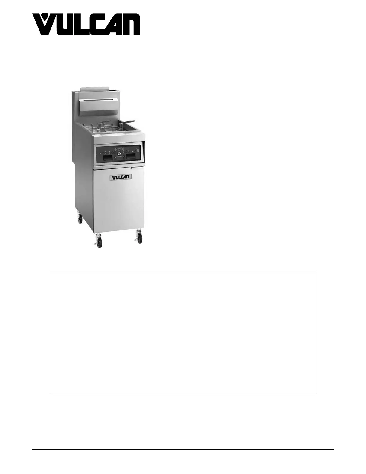
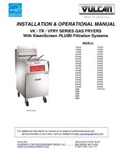
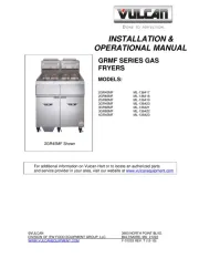
Vulcan 4VK45CF Manual

Vulcan Fryser 4VK45CF

Læs gratis den danske manual til Vulcan 4VK45CF (59 sider) i kategorien Fryser. Denne vejledning er vurderet som hjælpsom af 8 personer og har en gennemsnitlig bedømmelse på 4.6 stjerner ud af 4.5 anmeldelser. Har du et spørgsmål om Vulcan 4VK45CF, eller vil du spørge andre brugere om produktet?

Side 1/59
VK and TR GAS FRYERS W/Wo
KleenScreen PLUS
VK Series
TR Series
VFRY18 (after SN 481819109)
- NOTICE -
This Manual is prepared for the use of trained Hobart Service Technicians and should not
be used by those not properly qualified.
This manual is not intended to be all encompassing. If you have not attended a Hobart Service
School for this product, you should read, in its entirety, the repair procedure you wish to
perform to determine if you have the necessary tools, instruments and skills required to
perform the procedure. Procedures for which you do not have the necessary tools,
instruments and skills should be performed by a trained Hobart Service Technician.
The reproduction, transfer, sale or other use of this manual, without the express written
consent of Hobart, is prohibited.
This manual has been provided to you by ITW Food Equipment Group LLC ("ITW FEG")
without charge and remains the property of ITW FEG, and by accepting this manual you agree
that you will return it to ITW FEG promptly upon its request for such return at any time in the
future.
SERVICE MANUAL
A product of Vulcan-Hart 3600 North Point Blvd Baltimore, MD 21222
F45474 Rev. C (1020)
TABLE OF CONTENTS
Service Updates ............................................................................................ 4
SERVICE UPDATES ................................................................................... 4
TIS DOCUMENT LIST - VK & TR GAS FRYERS
........................................................ 4
GENERAL .................................................................................................. 6
INTRODUCTION ....................................................................................... 6
MODEL AND ML NUMBERS ............................................................................ 6
MODELS, FEATURES AND OPTIONS .................................................................. 7
KLEENSCREEN PLUS FILTRATION SYSTEM: (KSP) ................................................... 7
SERIAL NUMBER LOCATION .......................................................................... 8
CONTROL PANELS .................................................................................... 8
INSTALLATION ........................................................................................ 9
OPERATION ........................................................................................... 9
CLEANING ............................................................................................. 9
TOOLS ................................................................................................. 9
SPECIFICATIONS ...................................................................................... 9
REMOVAL AND REPLACEMENT OF PARTS .............................................................. 11
COVERS AND PANELS ............................................................................... 11
CONTROL PANEL (SOLID STATE AND COMPUTER) ............................................. 11
BASKET LIFT COVERS ........................................................................... 11
ANALOG CONTROL .................................................................................. 12
INTERFACE CONTROL - D AND C SERIES ........................................................... 13
POWER SWITCH - D AND C SERIES ................................................................. 13
TEMPERATURE PROBE .............................................................................. 14
HIGH LIMIT THERMOSTAT ........................................................................... 15
POWER SUPPLY BOX ................................................................................ 16
POWER SUPPLY BOX COMPONENTS BEFORE 12/1/12 .............................................. 17
IGNITION MODULE ............................................................................... 17
BLOWER CONTROL BOARD ..................................................................... 17
TIME DELAY TIMERS ............................................................................. 17
BLOWER RELAY ................................................................................. 17
FILTER RELAYS (24 VAC AND 120 VAC) ......................................................... 17
120 VOLT TRANSFORMER ....................................................................... 17
POWER SUPPLY BOX COMPONENTS AFTER 12/1/12 ............................................... 18
120 VOLT TRANSFORMER ....................................................................... 18
CONTROL BOARD ................................................................................ 18
FILTER RELAYS .................................................................................. 19
BURNER ASSEMBLY ................................................................................. 19
GAS VALVE .......................................................................................... 20
BASKET LIFT TUBE .................................................................................. 20
BASKET LIFT MOTOR ................................................................................ 20
BASKET LIFT CAM SWITCH .......................................................................... 21
BASKET LIFT CAM ................................................................................... 22
FILL SOLENOID VALVE (KSP) ........................................................................ 22
FILTER HOSE SWITCH (KSP) ........................................................................ 22
FILTER PUMP AND MOTOR (KLEENSCREEN FRYERS ONLY) ....................................... 23
DRAIN VALVE INTERLOCK SWITCH (DVI) ............................................................ 23
FRY TANK ............................................................................................ 24
SERVICE PROCEDURES AND ADJUSTMENTS ........................................................... 27
ELECTRIC CONNECTIONS ........................................................................... 27
HARMONIC TONE .................................................................................... 27
TEMPERATURE PROBE FAULT CODES .............................................................. 27
TEMPERATURE PROBE TEST ....................................................................... 27
COOKING CONTROL CALIBRATION .................................................................. 28
FLAME SENSE CURRENT CHECK PRIOR TO 12/1/12 ................................................ 28
VK and TR GAS FRYERS W/Wo KleenScreen PLUS
F45474 Rev. C (1020) Page 2 of 59
MODEL ML # MODEL ML # MODEL ML #
1TR45CF 136957 1TR65CF 136970 2TR85CF 136983
2TR45CF 136958 2TR65CF 136971 3TR85CF 136984
4TR65AF 136985 4TR65DF 136986 4TR65CF 136987
4TR85AF 136988 4TR85DF 136989 4TR85CF 136990
MODELS, FEATURES AND OPTIONS
MODEL
FEATURES OPTIONS
FRYER WIDTH
(INCHES)
SHORTENING
CAPACITY PER
FRYER (POUNDS)
BTU/HR/SECTION
AUTOMATIC
BASKET LIFTS
1VK/TR45A /D / C /
AF / DF / CF
15.5" 45 - 50 70,000 SINGLE OR DUAL
1VK/TR65A / D / C
AF / DF / CF
21.0" 65 - 70 80,000 SINGLE OR DUAL
1VK/TR85A / D / C /
AF / DF / CF
21.0" 85 - 90 90,000 SINGLE OR DUAL
2VK/TR45AF / DF /
CF
31.0" 45 - 50 70,000 SINGLE OR DUAL
3VK/TR45AF / DF /
CF
46.5" 45 - 50 70,000 SINGLE OR DUAL
4VK/TR45AF / DF /
CF
62.0" 45 - 50 70,000 SINGLE OR DUAL
2VK/TR65AF / DF /
CF
42.0" 65 - 70 80,000 SINGLE OR DUAL
3VK/TR65AF / DF /
CF
63.0" 65 - 70 80,000 SINGLE OR DUAL
4VK/TR65AF / DF /
CF
84.0" 65 - 70 80,000 SINGLE OR DUAL
2VK/TR85AF / DF /
CF
42.0" 85 - 90 90,000 SINGLE OR DUAL
3VKTR85AF / DF / CF 63.0" 85 - 90 90,000 SINGLE OR DUAL
4VK/TR85AF / DF /
CF
84.0" 85 - 90 90,000 SINGLE OR DUAL
KLEENSCREEN PLUS FILTRATION
SYSTEM: (KSP)
The KleenScreen PLUS® filtration system is
integrated
into the VK Series fryer battery. The filter is
housed in a pullout drawer assembly at the base of
the fryer. The filtering components in the drawer
include a stainless steel filter tank, a stainless steel
mesh filter screen with a stainless steel insert, a
suction tube and a knurled knob that holds the
assembly together. In addition, the KSP comes with a
second filtering system; a microfiltration fabric
envelope (3), a dedicated stainless steel insert and
stainless steel clip that holds the assembly together.
With the filter drawer closed, a self-sealing oil return
line provides the path to return the filtered shortening
back into the fry tank.
VK and TR GAS FRYERS W/Wo KleenScreen PLUS - GENERAL
Page 7 of 59 F45474 Rev. C (1020)
Fig. 39
NOTE: Make sure drain handle is in closed position.
If fry tank is full of shortening, carefully remove drain
handle. Make sure you do not turn handle to open
position. Doing so will allow shortening to drain on
floor or you.
4. Remove drain valve interlock switch bracket from
valve.
5. Remove screws holding the drain valve interlock
switch on bracket and take switch from bracket.
Fig. 40
6. Unplug drain valve interlock switch from wiring
harness and remove switch from fryer.
7. Reverse procedure to install and check for proper
operation.
FRY TANK
Disconnect the electrical power to
the machine and follow lockout /
tagout procedures.
Shut off the gas before servicing the
unit and follow lockout / tagout
procedures.
All gas joints disturbed during servicing must be
checked for leaks. Check with a soap and water
solution (bubbles). Do not use an open flame.
1. Remove BURNER ASSEMBLY.
VK and TR GAS FRYERS W/Wo KleenScreen PLUS - REMOVAL AND REPLACEMENT OF PARTS
F45474 Rev. C (1020) Page 24 of 59
Fig. 59
NOTE: For fryers built after 12/1/12, the fire timers
are replaced by a Ignition/Blower control board. The
high and low fire time settings are programmed into
the control board. If a fryer built before 12/1/12 has
been converted to the new Ignition/Blower control
board, there will be no adjustments.
AIR FILTER
A dirty air filter will prevent the correct amount of air
intake for the blower. The results are poor combustion
resulting in the fryer "puffing" severely.
To clean the air filter, remove the filter by pulling it off.
The clamp is only hand tightened. Clean air filter in
dishwasher or in sink with hot soapy water. Make sure
air filter is completely dry prior to reinstalling, making
sure that the filter is snug onto the blower intake. Make
sure NOT to tighten the clamp more than hand tight.
Fig. 60
SPARK GAP SETTING BEFORE
12/1/12
Fig. 61
The spark igniter rod should be set between 1/8" and
3/16" away from the mesh burner. This gap will allow
the igniter to produce the optimal spark required to
ignite the burner.
VK and TR GAS FRYERS W/Wo KleenScreen PLUS - SERVICE PROCEDURES AND ADJUSTMENTS
F45474 Rev. C (1020) Page 40 of 59


Produkt Specifikationer

Mærke: Vulcan
Kategori: Fryser
Model: 4VK45CF

Har du brug for hjælp?

Hvis du har brug for hjælp til Vulcan 4VK45CF stil et spørgsmål nedenfor, og andre brugere vil svare dig