SCREWDRIVER
SCREWDRIVER
SCREWDRIVER
SCREWDRIVERSCREWDRIVER
COUNTERTOP
COUNTERTOP
COUNTERTOP
COUNTERTOPCOUNTERTOP
WELLSLOK
WELLSLOK
WELLSLOK
WELLSLOKWELLSLOK
GASKET
GASKET
GASKET
GASKETGASKET
WARMER FLANGE
WARMER FLANGE
WARMER FLANGE
WARMER FLANGEWARMER FLANGE
TOP CUTOUT
TOP CUTOUT
TOP CUTOUT
TOP CUTOUTTOP CUTOUT
FRONT PANEL CUTOUT
FRONT PANEL CUTOUT
FRONT PANEL CUTOUT
FRONT PANEL CUTOUTFRONT PANEL CUTOUT
13/32 DIA
13/32 DIA
13/32 DIA
13/32 DIA13/32 DIA
17/64 DIA
17/64 DIA
17/64 DIA
17/64 DIA17/64 DIA
5/16 DIA
5/16 DIA
5/16 DIA
5/16 DIA5/16 DIA
5 3/16
5 3/16
5 3/16
5 3/165 3/16
(132)
(132)
(132)
(132)(132)
2 1/32
2 1/32
2 1/32
2 1/322 1/32
(279)
(279)
(279)
(279)(279)
8 1/2
8 1/2
8 1/2
8 1/28 1/2
(216)
(216)
(216)
(216)(216)
1 3/4
1 3/4
1 3/4
1 3/41 3/4
THE INSTALLATION OF RECOGNIZED COMPONENT UNITS
THE INSTALLATION OF RECOGNIZED COMPONENT UNITS
THE INSTALLATION OF RECOGNIZED COMPONENT UNITS
THE INSTALLATION OF RECOGNIZED COMPONENT UNITSTHE INSTALLATION OF RECOGNIZED COMPONENT UNITS
REQUIRES ADDITIONAL EVALUATIONS TO UNDERWRITERS
REQUIRES ADDITIONAL EVALUATIONS TO UNDERWRITERS
REQUIRES ADDITIONAL EVALUATIONS TO UNDERWRITERS
REQUIRES ADDITIONAL EVALUATIONS TO UNDERWRITERSREQUIRES ADDITIONAL EVALUATIONS TO UNDERWRITERS
LABORATORIES INC. STANDARDS.
LABORATORIES INC. STANDARDS.
LABORATORIES INC. STANDARDS.
LABORATORIES INC. STANDARDS.LABORATORIES INC. STANDARDS.
PRODUCT DIMENSIONS
PRODUCT DIMENSIONS
PRODUCT DIMENSIONS
PRODUCT DIMENSIONSPRODUCT DIMENSIONS
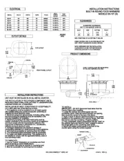
CUTOUT DETAILS
CUTOUT DETAILS
CUTOUT DETAILS
CUTOUT DETAILSCUTOUT DETAILS
90°C
90°C
90°C
90°C90°C
14 AWB Cu
14 AWB Cu
14 AWB Cu
14 AWB Cu14 AWB Cu
14 AWB Cu
14 AWB Cu
14 AWB Cu
14 AWB Cu14 AWB Cu
14 AWB Cu
14 AWB Cu
14 AWB Cu
14 AWB Cu14 AWB Cu
14 AWB Cu
14 AWB Cu
14 AWB Cu
14 AWB Cu14 AWB Cu
14 AWB Cu
14 AWB Cu
14 AWB Cu
14 AWB Cu14 AWB Cu
14 AWB Cu
14 AWB Cu
14 AWB Cu
14 AWB Cu14 AWB Cu
SINGLE
SINGLE
SINGLE
SINGLESINGLE
SINGLE
SINGLE
SINGLE
SINGLESINGLE
SINGLE
SINGLE
SINGLE
SINGLESINGLE
SINGLE
SINGLE
SINGLE
SINGLESINGLE
SINGLE
SINGLE
SINGLE
SINGLESINGLE
SINGLE
SINGLE
SINGLE
SINGLESINGLE
3.4
3.4
3.4
3.43.4
825
825
825
825825
120
120
120
120120
240
240
240
240240
SS-10TD
SS-10TD
SS-10TD
SS-10TDSS-10TD
SS-10TD
SS-10TD
SS-10TD
SS-10TDSS-10TD
SS-10TD
SS-10TD
SS-10TD
SS-10TDSS-10TD
SS-10T
SS-10T
SS-10T
SS-10TSS-10T
SS-10T
SS-10T
SS-10T
SS-10TSS-10T
SS-10T
SS-10T
SS-10T
SS-10TSS-10T
RATING
RATING
RATING
RATINGRATING
GAUGE
GAUGE
GAUGE
GAUGEGAUGE
FIELD
FIELD
FIELD
FIELDFIELD
TEMP.
TEMP.
TEMP.
TEMP.TEMP.
WIRING
WIRING
WIRING
WIRINGWIRING
PHASE
PHASE
PHASE
PHASEPHASE
AMPS
AMPS
AMPS
AMPSAMPS
WATTS
WATTS
WATTS
WATTSWATTS
VOLTS
VOLTS
VOLTS
VOLTSVOLTS
MODEL
MODEL
MODEL
MODELMODEL
ELECTRICAL
ELECTRICAL
ELECTRICAL
ELECTRICALELECTRICAL
WELLS/BLOOMFIELD * VERDI, NV
WELLS/BLOOMFIELD * VERDI, NV
WELLS/BLOOMFIELD * VERDI, NV
WELLS/BLOOMFIELD * VERDI, NVWELLS/BLOOMFIELD * VERDI, NV
MODELS SS-10T (D)
MODELS SS-10T (D)
MODELS SS-10T (D)
MODELS SS-10T (D)MODELS SS-10T (D)
BUILT-IN ROUND FOOD WARMERS
BUILT-IN ROUND FOOD WARMERS
BUILT-IN ROUND FOOD WARMERS
BUILT-IN ROUND FOOD WARMERSBUILT-IN ROUND FOOD WARMERS
INSTALLATION INSTRUCTIONS
INSTALLATION INSTRUCTIONS
INSTALLATION INSTRUCTIONS
INSTALLATION INSTRUCTIONSINSTALLATION INSTRUCTIONS
41941-2 REV (-)
41941-2 REV (-)
41941-2 REV (-)
41941-2 REV (-)41941-2 REV (-)
INSTALLATION INSTRUCTIONS
INSTALLATION INSTRUCTIONS
INSTALLATION INSTRUCTIONS
INSTALLATION INSTRUCTIONSINSTALLATION INSTRUCTIONS
TO INSTALL:
TO INSTALL:
TO INSTALL:
TO INSTALL:TO INSTALL:
IMPORTANT - DO NOT disconnect lead wires from the
IMPORTANT - DO NOT disconnect lead wires from the
IMPORTANT - DO NOT disconnect lead wires from the
IMPORTANT - DO NOT disconnect lead wires from theIMPORTANT - DO NOT disconnect lead wires from the
Control Panel when installing.
Control Panel when installing.
Control Panel when installing.
Control Panel when installing.Control Panel when installing.
1. Locate the warmer and control panel over the
1. Locate the warmer and control panel over the
1. Locate the warmer and control panel over the
1. Locate the warmer and control panel over the1. Locate the warmer and control panel over the
countertop cutout. Pass the control through the opening,
countertop cutout. Pass the control through the opening,
countertop cutout. Pass the control through the opening,
countertop cutout. Pass the control through the opening,countertop cutout. Pass the control through the opening,
then mount the control to the rear of the apron.
then mount the control to the rear of the apron.
then mount the control to the rear of the apron.
then mount the control to the rear of the apron.then mount the control to the rear of the apron.
2. Apply a bead of silicone adhesive/sealant to the gasket
2. Apply a bead of silicone adhesive/sealant to the gasket
2. Apply a bead of silicone adhesive/sealant to the gasket
2. Apply a bead of silicone adhesive/sealant to the gasket2. Apply a bead of silicone adhesive/sealant to the gasket
supplied on the underside of the warmer flange, then seat
supplied on the underside of the warmer flange, then seat
supplied on the underside of the warmer flange, then seat
supplied on the underside of the warmer flange, then seatsupplied on the underside of the warmer flange, then seat
the warmer onto the countertop. Properly position.
the warmer onto the countertop. Properly position.
the warmer onto the countertop. Properly position.
the warmer onto the countertop. Properly position.the warmer onto the countertop. Properly position.
3. From underneath, insert a screwdriver into the "slots" on
3. From underneath, insert a screwdriver into the "slots" on
3. From underneath, insert a screwdriver into the "slots" on
3. From underneath, insert a screwdriver into the "slots" on3. From underneath, insert a screwdriver into the "slots" on
the wellslok frame and twist the "ears" outward to secure
the wellslok frame and twist the "ears" outward to secure
the wellslok frame and twist the "ears" outward to secure
the wellslok frame and twist the "ears" outward to securethe wellslok frame and twist the "ears" outward to secure
the flange tightly to the countertop (see detail).
the flange tightly to the countertop (see detail).
the flange tightly to the countertop (see detail).
the flange tightly to the countertop (see detail).the flange tightly to the countertop (see detail).
4. Mount the master control panel to the front of the
4. Mount the master control panel to the front of the
4. Mount the master control panel to the front of the
4. Mount the master control panel to the front of the4. Mount the master control panel to the front of the
counter apron using the screws supplied.
counter apron using the screws supplied.
counter apron using the screws supplied.
counter apron using the screws supplied.counter apron using the screws supplied.
INSTALLER MUST MEET CONDITIONS OF ACCEPTABILITY
INSTALLER MUST MEET CONDITIONS OF ACCEPTABILITY
INSTALLER MUST MEET CONDITIONS OF ACCEPTABILITY
INSTALLER MUST MEET CONDITIONS OF ACCEPTABILITYINSTALLER MUST MEET CONDITIONS OF ACCEPTABILITY
OUTLINED BELOW UPON INSTALLATION:
OUTLINED BELOW UPON INSTALLATION:
OUTLINED BELOW UPON INSTALLATION:
OUTLINED BELOW UPON INSTALLATION:OUTLINED BELOW UPON INSTALLATION:
1. This appliance shall be installed in an all metal counter
1. This appliance shall be installed in an all metal counter
1. This appliance shall be installed in an all metal counter
1. This appliance shall be installed in an all metal counter1. This appliance shall be installed in an all metal counter
with suitable wiring and control enclosures conforming to
with suitable wiring and control enclosures conforming to
with suitable wiring and control enclosures conforming to
with suitable wiring and control enclosures conforming towith suitable wiring and control enclosures conforming to
national and local electrical codes.
national and local electrical codes.
national and local electrical codes.
national and local electrical codes.national and local electrical codes.
2. Electrical component temperatures, including wiring, within
2. Electrical component temperatures, including wiring, within
2. Electrical component temperatures, including wiring, within
2. Electrical component temperatures, including wiring, within2. Electrical component temperatures, including wiring, within
and surrounding the appliance must be monitored in the
and surrounding the appliance must be monitored in the
and surrounding the appliance must be monitored in the
and surrounding the appliance must be monitored in theand surrounding the appliance must be monitored in the
end use installation for suitability.
end use installation for suitability.
end use installation for suitability.
end use installation for suitability.end use installation for suitability.
3. Electrical grounding of all dead metal parts must be
3. Electrical grounding of all dead metal parts must be
3. Electrical grounding of all dead metal parts must be
3. Electrical grounding of all dead metal parts must be3. Electrical grounding of all dead metal parts must be
reliably connected to the grounding means of the appliance
reliably connected to the grounding means of the appliance
reliably connected to the grounding means of the appliance
reliably connected to the grounding means of the appliancereliably connected to the grounding means of the appliance
and must comply with the requirements outlined in the
and must comply with the requirements outlined in the
and must comply with the requirements outlined in the
and must comply with the requirements outlined in theand must comply with the requirements outlined in the
appropriate Underwriters Laboratories Inc. classification,
appropriate Underwriters Laboratories Inc. classification,
appropriate Underwriters Laboratories Inc. classification,
appropriate Underwriters Laboratories Inc. classification,appropriate Underwriters Laboratories Inc. classification,
national and local electrical codes.
national and local electrical codes.
national and local electrical codes.
national and local electrical codes.national and local electrical codes.
4. Increased clearances are required if storage of
4. Increased clearances are required if storage of
4. Increased clearances are required if storage of
4. Increased clearances are required if storage of4. Increased clearances are required if storage of
combustible materials is in close proximity to this appliance.
combustible materials is in close proximity to this appliance.
combustible materials is in close proximity to this appliance.
combustible materials is in close proximity to this appliance.combustible materials is in close proximity to this appliance.
5. Unit shall be accessible for servicing from the bottom.
5. Unit shall be accessible for servicing from the bottom.
5. Unit shall be accessible for servicing from the bottom.
5. Unit shall be accessible for servicing from the bottom.5. Unit shall be accessible for servicing from the bottom.
6. The name/rating plate information shall be accessible.
6. The name/rating plate information shall be accessible.
6. The name/rating plate information shall be accessible.
6. The name/rating plate information shall be accessible.6. The name/rating plate information shall be accessible.
7. For water and waste connections: This appliance is to
7. For water and waste connections: This appliance is to
7. For water and waste connections: This appliance is to
7. For water and waste connections: This appliance is to7. For water and waste connections: This appliance is to
be installed to comply with the applicable federal, state or
be installed to comply with the applicable federal, state or
be installed to comply with the applicable federal, state or
be installed to comply with the applicable federal, state orbe installed to comply with the applicable federal, state or
local plumbing codes.
local plumbing codes.
local plumbing codes.
local plumbing codes.local plumbing codes.
TO FABRICATE:
TO FABRICATE:
TO FABRICATE:
TO FABRICATE:TO FABRICATE:
1. Lay out "cutout" dimensions on countertop and front
1. Lay out "cutout" dimensions on countertop and front
1. Lay out "cutout" dimensions on countertop and front
1. Lay out "cutout" dimensions on countertop and front1. Lay out "cutout" dimensions on countertop and front
apron as shown in cutout details above.
apron as shown in cutout details above.
apron as shown in cutout details above.
apron as shown in cutout details above.apron as shown in cutout details above.
2. Cut and/or drill holes as required in countertop and
2. Cut and/or drill holes as required in countertop and
2. Cut and/or drill holes as required in countertop and
2. Cut and/or drill holes as required in countertop and2. Cut and/or drill holes as required in countertop and
3. Must be accessible for servicing from the bottom.
3. Must be accessible for servicing from the bottom.
3. Must be accessible for servicing from the bottom.
3. Must be accessible for servicing from the bottom.3. Must be accessible for servicing from the bottom.
UNIT MUST BE INSTALLED IN AN ALL METAL COUNTER.
UNIT MUST BE INSTALLED IN AN ALL METAL COUNTER.
UNIT MUST BE INSTALLED IN AN ALL METAL COUNTER.
UNIT MUST BE INSTALLED IN AN ALL METAL COUNTER.UNIT MUST BE INSTALLED IN AN ALL METAL COUNTER.
METAL SHIELD
METAL SHIELD
METAL SHIELD
METAL SHIELDMETAL SHIELD
1/2 NPT
1/2 NPT
1/2 NPT
1/2 NPT1/2 NPT
(TD MODELS)
(TD MODELS)
(TD MODELS)
(TD MODELS)(TD MODELS)
NOTE: * CONTROL MUST NOT BE MOUNTED
NOTE: * CONTROL MUST NOT BE MOUNTED
NOTE: * CONTROL MUST NOT BE MOUNTED
NOTE: * CONTROL MUST NOT BE MOUNTEDNOTE: * CONTROL MUST NOT BE MOUNTED
IN THIS HIGH TEMPERATURE AREA.
IN THIS HIGH TEMPERATURE AREA.
IN THIS HIGH TEMPERATURE AREA.
IN THIS HIGH TEMPERATURE AREA.IN THIS HIGH TEMPERATURE AREA.
8 1/2
8 1/2
8 1/2
8 1/28 1/2
(216)
(216)
(216)
(216)(216)
(305)
(305)
(305)
(305)(305)
8 3/4
8 3/4
8 3/4
8 3/48 3/4
(222)
(222)
(222)
(222)(222)
4 7/16
4 7/16
4 7/16
4 7/164 7/16
(113)
(113)
(113)
(113)(113)
SUGGESTED CLEARANCES
SUGGESTED CLEARANCES
SUGGESTED CLEARANCES
SUGGESTED CLEARANCESSUGGESTED CLEARANCES
NOTE: DEPENDING ON THE INSTALLATION,
NOTE: DEPENDING ON THE INSTALLATION,
NOTE: DEPENDING ON THE INSTALLATION,
NOTE: DEPENDING ON THE INSTALLATION,NOTE: DEPENDING ON THE INSTALLATION,
CLEARANCES CAN BE FURTHER REDUCED
CLEARANCES CAN BE FURTHER REDUCED
CLEARANCES CAN BE FURTHER REDUCED
CLEARANCES CAN BE FURTHER REDUCEDCLEARANCES CAN BE FURTHER REDUCED
UPON EVALUATIONS TO UL STANDARDS.
UPON EVALUATIONS TO UL STANDARDS.
UPON EVALUATIONS TO UL STANDARDS.
UPON EVALUATIONS TO UL STANDARDS.UPON EVALUATIONS TO UL STANDARDS.
WHEN CONTROL BOX IS LOCATED BELOW THE
WHEN CONTROL BOX IS LOCATED BELOW THE
WHEN CONTROL BOX IS LOCATED BELOW THE
WHEN CONTROL BOX IS LOCATED BELOW THEWHEN CONTROL BOX IS LOCATED BELOW THE
UNIT, FRONT CLEARANCE CAN BE 2 INCHES.
UNIT, FRONT CLEARANCE CAN BE 2 INCHES.
UNIT, FRONT CLEARANCE CAN BE 2 INCHES.
UNIT, FRONT CLEARANCE CAN BE 2 INCHES.UNIT, FRONT CLEARANCE CAN BE 2 INCHES.
CLEARANCES
CLEARANCES
CLEARANCES
CLEARANCESCLEARANCES
BACK
BACK
BACK
BACKBACK SIDE
SIDE
SIDE
SIDESIDE BOTTOM
BOTTOM
BOTTOM
BOTTOMBOTTOM FRONT
FRONT
FRONT
FRONTFRONT
(25)
(25)
(25)
(25)(25) (216)
(216)
(216)
(216)(216)
8 1/2
8 1/2
8 1/2
8 1/28 1/2
(102)
(102)
(102)
(102)(102)
SEE CONDITIONS OF ACCEPTIBILITY BELOW
SEE CONDITIONS OF ACCEPTIBILITY BELOW
SEE CONDITIONS OF ACCEPTIBILITY BELOW
SEE CONDITIONS OF ACCEPTIBILITY BELOWSEE CONDITIONS OF ACCEPTIBILITY BELOW
UNIT TO THE NEAREST SURFACE
UNIT TO THE NEAREST SURFACE
UNIT TO THE NEAREST SURFACE
UNIT TO THE NEAREST SURFACEUNIT TO THE NEAREST SURFACE
INCHES
INCHES
INCHES
INCHESINCHES