ACTi E217 Manual
Læs gratis den danske manual til ACTi E217 (45 sider) i kategorien Overvågningskamera. Denne vejledning er vurderet som hjælpsom af 34 personer og har en gennemsnitlig bedømmelse på 4.8 stjerner ud af 17.5 anmeldelser.
Har du et spørgsmål om ACTi E217, eller vil du spørge andre brugere om produktet?

Produkt Specifikationer
| Mærke: | ACTi |
| Kategori: | Overvågningskamera |
| Model: | E217 |
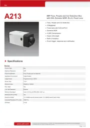
| Type: | IP-sikkerhedskamera |
| Bredde: | 142 mm |
| Dybde: | 65 mm |
| Højde: | 67 mm |
| Vægt: | 425 g |
| Produktfarve: | Black, Grey, White |
| Kompatible hukommelseskort: | MicroSDHC |
| Formfaktor: | Kasse |
| Understøttede videotilstande: | 1080p |
| Relativ luftfugtighed ved drift (H-H): | 10 - 85 % |
| Ethernet LAN-porte (RJ-45): | 1 |
| Ethernet LAN: | Ja |
| Understøttede lydformater: | G.711, PCM |
| Driftstemperatur (T-T): | -10 - 50 °C |
| Maksimal opløsning: | 1920 x 1080 pixel |
| Understøttede grafikopløsninger: | 320 x 240,640 x 480 (VGA),1280 x 720 (HD 720),1920 x 1080 (HD 1080) |
| Forbindelsesteknologi: | Ledningsført |
| Certificering: | CE, FCC, UL |
| Kabelteknologi: | 10/100Base-T(X) |
| Netværksstandarder: | IEEE 802.3af |
| DC-in-stik: | Ja |
| Understøttede netværksprotokoller: | TCP, UDP, HTTP, HTTPS, DHCP, PPPoE, RTP, RTSP, IPv6, DNS, DDNS, NTP, ICMP, ARP, IGMP, SMTP, FTP, UPnP, SNMP, Bonjour |
| Knap til nulstilling: | Ja |
| IP-adresse filtrering: | Ja |
| LED-indikatorer: | Ja |
| Strømkilde type: | PoE |
| Monteringstype: | Loft/væg/pæl |
| Indbygget kortlæser: | Ja |
| Full HD: | Ja |
| Video komprimeringsformater: | H.264, M-JPEG |
| Hvidbalance: | Auto, Manual |
| Sensortype: | CMOS |
| Billedstabilisator: | Ja |
| Samlet antal megapixels: | 2.38 MP |
| Støjreduktion: | Ja |
| Fokus: | Vejledning |
| Bredt dynamikområde (WDR): | Ja |
| Dag/nat funktion: | Ja |
| Infrarød (IR) cut-off filter: | Ja |
| Minimumsbelysning: | 0.05 Lux |
| Antal sensorer: | 1 |
| Optisk sensorstørrelse: | 1/2.8 " |
| Antal effektive pixels (HxV): | 1944 x 1224 pixel |
| Maksimale blænderåbning tal: | 2 |
| Fast brændvidde: | 2.93 mm |
| Nattesyn: | Ingen |
| Billedhastighed: | 60 fps |
| Forstærkningskontroltype: | Automatisk |
| Justering af billedkvalitet: | Brightness, Contrast, Sharpness |
| Fortrolighedspolitik maskering: | Ja |
| Tekst billedtekst overlay: | Ja |
| Ethernet-grænsefladetype: | Hurtigt ethernet |
| HTTPS -kryptering: | Ja |
| Antal kameraer: | 1 |
| Kameraets lukkerhastighed: | 1/5 - 1/10000 sek./side |
| Signal/støjforhold: | 52 dB |
| Kamera lukker type: | Elektronisk |
| Videostreaming: | Ja |
| Antal linser: | 1 |
| Streaming metode: | Multicast |
| Beskyttelse af adgangskode: | Ja |
| Intelligent Video Surveillance (IVS) systemfunktioner: | Crossing line, Face detection, Intrusion, Missing object |
| Advarsel notifikationstype: | E-mail, Snapshot alert message |
| Bit-rate: | 128 Kbps - 12 Mbps |
| Klemrække port: | Ja |
| Adgangskodebeskyttelse type: | Bruger |
| RS-485-porte: | 1 |
| Prøvetagningshastighed: | 8 kHz |
| Strømforbrug (Power over Ethernet (PoE)): | 7 W |
| Objektivets synsvinkel, vandret: | 101.3 ° |
| Justering af lukkertid: | Auto/manuel |
| Anti-flimmer: | Ja |
| Audiosporing: | Ja |
| 3D NR (støjreduktion): | Ja |
| Bitrate kontrol: | Constant Bit Rate (CBR), Variable Bit Rate (VBR) |
| Antal tv-linjer (vandret): | 1100 |
Har du brug for hjælp?
Hvis du har brug for hjælp til ACTi E217 stil et spørgsmål nedenfor, og andre brugere vil svare dig
Overvågningskamera ACTi Manualer


Overvågningskamera Manualer
- Turing
- Ebode
- MicroView
- Marquant
- Vimtag
- B & S Technology
- ZKTeco
- ElectriQ
- Schwaiger
- EZVIZ
- Tecno
- Powerfix
- Beafon
- JouSecu
- Belkin
Nyeste Overvågningskamera Manualer