ACTi I912 Manual
Læs gratis den danske manual til ACTi I912 (43 sider) i kategorien Overvågningskamera. Denne vejledning er vurderet som hjælpsom af 11 personer og har en gennemsnitlig bedømmelse på 4.6 stjerner ud af 6 anmeldelser.
Har du et spørgsmål om ACTi I912, eller vil du spørge andre brugere om produktet?

Produkt Specifikationer
| Mærke: | ACTi |
| Kategori: | Overvågningskamera |
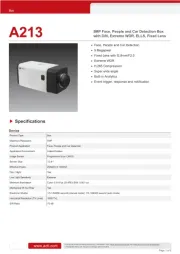
| Model: | I912 |
| Type: | IP-sikkerhedskamera |
| Højde: | 163.3 mm |
| Vægt: | 1573 g |
| Produktfarve: | Hvid |
| Kompatible hukommelseskort: | MicroSDHC, MicroSDXC |
| Wi-Fi: | Ingen |
| Bluetooth: | Ingen |
| Formfaktor: | Kuppel |
| Relativ luftfugtighed ved drift (H-H): | 10 - 85 % |
| Ethernet LAN-porte (RJ-45): | 1 |
| Ethernet LAN: | Ja |
| Webbrowser: | Ja |
| Driftstemperatur (T-T): | -20 - 50 °C |
| Maksimal opløsning: | 2688 x 1520 pixel |
| Beskyttelsesfunktioner: | Hærværkssikret |
| Understøttede grafikopløsninger: | 320 x 240,640 x 480 (VGA),800 x 600 (SVGA),1280 x 720 (HD 720),1920 x 1080 (HD 1080),2560 x 1440,2688 x 1520 |
| Forbindelsesteknologi: | Ledningsført |
| Certificering: | CE, FCC, UL |
| Netværksstandarder: | IEEE 802.1x, IEEE 802.3at |
| Understøttede netværksprotokoller: | IPv4/v6, TCP, UDP, DHCP, PPPoE, HTTP, HTTPS, DNS, DDNS, NTP, RTP, RTSP, RTCP, SMTP, FTP, IGMP, ICMP, ARP, Bonjour, UPnP, QoS, SNMP, IEEE 802.1X |
| Webbaseret administration: | Ja |
| Servicekvalitet support (QoS): | Ja |
| IP-adresse filtrering: | Ja |
| Strømkilde type: | DC, PoE |
| Monteringstype: | Loft/væg |
| Diameter: | 150 mm |
| Indbygget kortlæser: | Ja |
| Indbygget HDD: | Ingen |
| Video komprimeringsformater: | H.264, M-JPEG |
| Understøttet placering: | Indendørs |
| Mikrofonindgang: | Ja |
| Sensortype: | CMOS |
| Samlet antal megapixels: | 4 MP |
| Støjreduktion: | Ja |
| Lydsystem: | 2-vejs |
| Optisk zoom: | 33 x |
| Autofokus: | Ja |
| Firmware kan opgraderes: | Ja |
| Hældningsvinkelområde: | 0 - 180 ° |
| Progressiv scanning: | Ja |
| Voice codecs: | G.711, PCM |
| Bredt dynamikområde (WDR): | Ja |
| Dag/nat funktion: | Ja |
| Infrarød (IR) cut-off filter: | Ja |
| IK kode: | IK09 |
| Kamerapanorering kontrol: | Ja |
| Kontrol af kamerahældning: | Ja |
| Minimumsbelysning: | 0.05 Lux |
| Panoreringsområde: | 0 - 360 ° |
| Antal sensorer: | 1 |
| Optisk sensorstørrelse: | 1/3 " |
| Antal effektive pixels (HxV): | 2688 x 1520 pixel |
| Zoom kapacitet: | Ja |
| Maksimale blænderåbning tal: | 1.6 |
| Billedhastighed: | 30 fps |
| Forstærkningskontroltype: | Automatisk |
| Justering af billedkvalitet: | Brightness, Contrast, Sharpness |
| Fortrolighedspolitik maskering: | Ja |
| Tekst billedtekst overlay: | Ja |
| Bevægelsessensor (video): | Ja |
| HTTPS -kryptering: | Ja |
| DC udgangsspænding: | 12 |
| Antal kameraer: | 1 |
| Brændviddeområde: | 4.5-148.5 mm |
| Kameraets lukkerhastighed: | 1/15-1/2000, 1/15-1/10000 sek./side |
| Mindste blænderåbnimg tal: | 5 |
| Kamera lukker type: | Elektronisk |
| Videostreaming: | Ja |
| Antal linser: | 1 |
| Beskyttelse af adgangskode: | Ja |
| PTZ-kontrol: | Ja |
| Hældningshastighed: | 32 grader i sekundet |
| Panoreringshastighed: | 32 grader i sekundet |
| Intelligent Video Surveillance (IVS) systemfunktioner: | Face detection, Missing object, People counting |
| Bit-rate: | 28Kbps - 6Mbps |
| Prøvetagningshastighed: | 8 kHz |
| Strømforbrug (Power over Ethernet (PoE)): | 12.6 W |
| Flip & spejl: | Ja |
| Objektivets synsvinkel, vandret: | 58.78 ° |
| Objektivets synsvinkel, lodret: | 35.39 ° |
| Justering af lukkertid: | Auto/manuel |
| PTZ-protokoller: | Pelco-P/D |
| Forudindstillet hastighed: | 480 grader i sekundet |
| Støjreduktionsteknologi: | 3D støjreduktion |
| Adfærdsanalyse: | Line crossing detection, Unattended baggage detection |
| PTZ-tilstande: | Forudindstillet punkt |
| Bitrate kontrol: | Constant Bit Rate (CBR)/Variable Bit Rate (VBR) |
Har du brug for hjælp?
Hvis du har brug for hjælp til ACTi I912 stil et spørgsmål nedenfor, og andre brugere vil svare dig
Overvågningskamera ACTi Manualer

Overvågningskamera Manualer
- Sony
- Busch-Jaeger
- BirdDog
- EKO
- Aida
- Sir Gawain
- Evolveo
- Seneca
- Hamlet
- Hombli
- SPC
- Inovonics
- Lutec
- Gewiss
- Adj
Nyeste Overvågningskamera Manualer