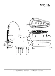
AKG C417 Manual

AKG Mikrofon C417

Læs nedenfor 📖 manual på dansk for AKG C417 (68 sider) i kategorien Mikrofon. Denne guide var nyttig for 15 personer og blev bedømt med 4.5 stjerner i gennemsnit af 2 brugere

Side 1/68
C417
III
BEDIENUNGSHINWEISE . . . . . . . . . . . . . S. 2
Bitte vor Inbetriebnahme des Gerätes lesen!
USER INSTRUCTIONS . . . . . . . . . . . . . . . p. 1 3
Please read the manual before using the equipment!
MODE DEMPLOI . . . . . . . . . . . . . . . . . . . . . . p. 24
Veuillez lire cette notice avant d’utiliser le système!
ISTRUZIONI PER L’USO . . . . . . . . . . . . . p. 35
Prima di utilizzare l’apparecchio, leggere il manuale!
MODO DE EMPLEO . . . . . . . . . . . . . . . . . . . p. 46
Antes de utilizar el equipo, sirvase leer el manual!
INSTRUÇÕES DE USO . . . . . . . . . . . . . . . p. 5 7
Favor leia este manual antes de usar o equipamento!
2
1.1 Sicherheits -
hinweis
1.2
Lieferumfang
1.3 Empfohlenes
Zubehör
1.4 Besondere
Merkmale
Überprüfen Sie bitte, ob das Gerät, an das Sie das
Mikrofon anschließen möchten, den gültigen Si-
cherheitsbestimmungen entspricht und mit einer
Sicherheitserdung versehen ist.
Kontrollieren Sie bitte, ob die Verpackung alle
oben angeführten Teile enthält. Falls etwas fehlt,
wenden Sie sich bitte an Ihren AKG-Händler.
Professionelles Miniatur-Ansteckmikrofon.
Kondensatorwandler mit kugelförmiger Richt-
charakteristik für natürlichen Klang.
Weiter Übertragungsbereich für Sprache, Ge-
sang, Violine.
1 Sicherheitshinweis/Beschreibung
1 C 417 III 1 W 407 1 H 40/1 1 H 41
Mikrofonkabel 10 m 2-poligMK 9/10:
geschirmtes Kabel mit XLR-Stecker
und XLR-Kupplung
Phantomspeiseadapter MPA III L
Batteriespeisegeräte
B 29 L, B 15
Phantomspeise -
ge räte N 62 E,
N 66 E, B 18
3
Geeignet zur Befestigung an der Kleidung oder
direkt am Kopf der Anwenderin/des Anwen-
ders.
Das C 417III ist ein professionelles Miniatur-Kon-
densator-Ansteckmikrofon mit kugelförmiger
Richtcharakteristik. Auf Grund des weiten Über-
tragungsbereichs von 20 bis 20.000 Hz, der gerin-
gen Verzerrungen bei hohem Schalldruck sowie
der kleinen Abmessungen und des universell an-
wendbaren Zubehörs eignet sich das Mikrofon
ideal für alle Anwendungen, wo unauffällige Mi-
krofontechnik und große Bewegungsfreiheit der
Anwenderin/des Anwenders gefordert werden.
Zwei verschiedene Farbvarianten ermöglichen die
fast unsichtbare Integration des Mikrofons in die
Maske von SchauspielerInnen und SängerInnen.
Ein externer Windschutz r die mpfung von
Windgeräuschen bei Einsatz im Freien ist im Lie-
ferumfang enthalten.
Das C 417III ist in drei Ausführungen erhältlich:
Mit 3-poligem XLR-Stecker mit eingebautem
Adapter für Universal-Phantomspeisung von 9
bis 52 V.
Mit verriegelbarem Mini-XLR-Stecker zum An-
schluss an Batteriespeisegerät B 29 L, Phan-
tomspeiseadapter MPA III L oder AKG-
Taschen sender.
Wie C 417III L, Kabel und Mikrofonkopf pink.
1 Beschreibung
1.5 Kurz -
beschreibung
1.6 Varianten
C 417III PP
C 417III L
C 417III PL
4
2.1 Einleitung
Wichtig!
2.2 C 417
III PP
2.2.1 Anschluss
an symmetri-
sche Eingänge
Siehe Abb. 1.
Das C 417III PP ist ein Kondensatormikrofon und
benötigt daher eine Stromversorgung.
Wenn Sie andere als die von AKG empfoh-
lenen Speisegeräte verwenden, kann das
Mikrofon beschädigt werden und erlischt
die Garantie.
1. Stecken Sie den Phantomspeiseadapter (1) am
Mikrofonkabel an einen symmetrischen XLR-
Mikrofoneingang mit Phantom speisung an.
2. Schalten Sie die Phantomspeisung ein. (Lesen
Sie dazu in der Betriebsanleitung des jeweili-
gen Gerätes nach.)
3. Wenn Ihr Mischpult keine Phantom -
speisung besitzt, stecken Sie den
Phantomspeiseadapter (1) an ein optionales
AKG-Phantom speise gerät (2) (N 62 E, N 66 E,
B 18, B 15) an und verbinden Sie das
Phantomspeisegerät mit Hilfe eines XLR-
Kabels (3) (z.B. AKG MK 9/10 - nicht mitgelie-
fert) mit einem symmetrischen Eingang.
2 Anschluss
XLR
1
2
1
3
Phantom
XLR
Abb. 1: Anschluss an symmetrischen Eingang
5
2.2.2 Anschluss
an asymmetri-
sche Eingänge
Siehe Abb. 2.
Hinweis:
2.3 C 417III L/PL
2.3.1 Anschluss
mittels B 29 L
Siehe Abb.3.
Kabel anstecken:
Phantomspeisegeräte (2) von AKG können Sie auch
an einen asymmetrischen Eingang an schlien.
Verwenden Sie dazu ein Kabel (3) mit XLR-
Stecker (weiblich) und Mono-Klinkenstecker:
1. Verbinden Sie im XLR-Stecker (4) mittels einer
Drahtbrücke Stift 1 mit Stift 3 und mit der
Abschirmung.
2. Verbinden Sie die innere Ader des Kabels mit
Stift 2 des XLR-Steckers (4) und der Spitze
des Klinkensteckers (5).
Beachten Sie, dass asymmetrische Kabel Ein-
streuungen aus Magnetfeldern (von Netz- und
Lichtkabeln, Elektromotoren usw.) wie eine An-
tenne aufnehmen können . Bei Kabeln, die n-
ger als 5 m sind, kann dies zu Brumm- und
ähnlichen Störgeräuschen führen.
Mit dem optionalen Batteriespeisegerät B 29 L
können Sie das Mikrofon an symmetrische oder
asymmetrische Eingänge ohne Phantomspeisung
anschliessen.
1. Stecken Sie den Mini-XLR-Stecker (1) am
Mikrofonkabel bis zum Anschlag in eine der
beiden Mini-XLR-Buchsen am B 29 L (2).
Der Stecker (1) verriegelt sich automatisch.
2 Anschluss
XLR Phantom
1
2
3
45
Abb. 2: Anschluss an asymmetrischen Eingang
6
Kabel abziehen:
Wichtig!
Siehe Abb. 3.
Symmetrischer
Eingang:
Asymmetrischer
Eingang:
2.3.2 Anschluss
mittels MPA III L
Siehe Abb. 4.
Kabel abziehen:
Zum Abziehen des Kabels drücken Sie auf
den Entriegelungsknopf am Mini XLR-Stecker
(1) und ziehen Sie den Stecker (1) aus der
Buchse heraus.
Um das Kabel nicht zu beschädigen, zie-
hen Sie niemals am Kabel selbst!
2. Verbinden Sie das B 29 L (2) mit dem
gewünschten Eingang.
Zum Anschluss an einen symmetrischen
Eingang verwenden Sie ein handelsübli-
ches XLR-Kabel (3).
Siehe Kapitel 2.2.2.
1. Stecken Sie den Mini-XLR-Stecker (1) am
Mikrofonkabel bis zum Anschlag in die Mini-
XLR-Kupplung (2) am Anschlusskabel des
MPA III L (3).
Der Stecker (1) verriegelt sich automatisch.
Siehe Kapitel 2.3.1.
2. Stecken Sie den MPA III L (3) an einen sym-
metrischen XLR-Mikrofoneingang mit Phan -
tomspeisung an.
3. Schalten Sie die Phantomspeisung ein. (Lesen
Sie dazu in der Betriebsanleitung des jeweili-
gen Gerätes nach.)
2 Anschluss
B 29 L
1
2
3
45
Abb. 3: Anschluss-Schema mit B 29 L
7
Siehe Abb. 4.
2.3.3 Anschluss an
Taschensender
4. Wenn Ihr Mischpult keine Phantom -
speisung besitzt, stecken Sie den MPA III L
(3) an ein optionales AKG-Phantom speise -
gerät (4) (N 62 E, N 66 E, B 18, B 15) an und
verbinden Sie das Phantomspeisegerät (4) mit
Hilfe eines XLR-Kabels (5) (z.B. AKG MK 9/10
- nicht mitgeliefert) mit einem symmetrischen
Eingang.
Lesen Sie in der Bedienungsanleitung Ihres
Taschensenders nach.
2 Anschluss
Mini XLR Mini XLR MPA
MPA
3
Phantom
4
123
5
Abb. 4: Anschluss-Schema mit MPA III L
8
3.1 Einleitung
3.2 Anwendung
als Lavalier -
mikrofon
Abb. 5: Mikrofon
an Ansteckclip (a)
und Anstecknadel
(b) befestigen
Abb. 6: Mikrofon
nahe beim Mund
befestigen
Der große Vorteil eines an der Kleidung oder in der
Maske befestigten Mikrofons besteht darin, dass
der Abstand zwischen dem Mikrofon und dem
Mund der Anwenderin/des Anwenders unabhän-
gig von deren/dessen Bewegungen immer gleich
bleibt und damit keine Pegelschwankungen zu
befürchten sind. Die Bewegungsfreiheit bleibt er-
halten, die Hände bleiben frei.
1. Klemmen Sie das Kabel unmittelbar hinter dem
Mikrofongehäuse in eine der Aufnahmerillen
des mitgelieferten Ansteckclips H 40/1 (Abb.
5a) bzw. der mitgelieferten Anstecknadel H 41
(Abb. 5b).
2. Befestigen Sie das Mikrofon so nahe wie mög-
lich beim Mund der Rednerin/des Redners an
3 Anwendung
a b
min.
9
Hinweis:
3.3 Anwendung
als Aufnahme-
oder
Stützmikrofon
3.4 Theater,
Musical, Oper
Abb. 7: Mikrofon in
der Maske
integriert
der Kleidung, z.B. am Revers.
Je geringer der Abstand zwischen dem Mikro-
fon und der Schallquelle, umso geringer ist die
Gefahr akustischer Rückkopplungen.
1. Klemmen Sie das Kabel unmittelbar hinter dem
Mikrofongehäuse in die entsprechende Auf-
nahme des mitgelieferten Ansteckclips H 40/1
(Abb. 5a) bzw. der mitgelieferten Anstecknadel
H 41 (Abb. 5b).
2. Befestigen Sie das Mikrofon an einem geeig-
neten Dekorationsteil (z.B. Kulisse, Hinter-
grund, Vorhang o.ä.).
Befestigen Sie das Mikrofon in der Maske mög-
lichst nahe beim Mund.
Abb. 7 zeigt eine Möglichkeit der Positionierung.
Je nach den Erfordernissen der Inszenierung kön-
nen Sie das Mikrofon z.B. auch an der Stirn an-
bringen.
3 Anwendung
10
3.5 Violine
Abb. 8: Abnahme
der Violine
Siehe Abb. 8. Falls das Mikrofon nicht an der Violine selbst befe-
stigt werden kann oder darf, können Sie das Mi-
krofon mit Mastix an der Wange der Geigerin/
des Geigers befestigen.
Diese Methode hat folgende Vorteile:
Das Mikrofon ist nicht an der Violine selbst be-
festigt, daher wird der Klang der Violine nicht
beeinflusst.
Es besteht keine Gefahr, die Violine durch Kle-
beband o.ä. zu beschädigen.
Die Violine benötigt keinerlei lästige Kabelver-
bindung.
Reinigen Sie das Gehäuse des Mikrofons mit ei-
nem mit Wasser befeuchteten Tuch.
3 Anwendung
4 Reinigung
11
5 Fehlerbehebung
Fehler
Kein Ton:
Verzerrungen:
Mögliche Ursache
1. Mischpult und/oder
Verstärker ausge-
schaltet.
2. Kanal-Fader oder
Summenpegelregler
am Mischpult oder
Lautstärkeregler des
Verstärkers steht auf
Null.
3. Mikrofon nicht an
Mischpult oder
Verstärker ange-
schlossen.
4. Kabelstecker nicht
richtig angesteckt.
5. Kabel defekt.
6. Keine Speise -
spannung.
1. Gain-Regler am
Mischpult zu weit
aufgedreht.
2. Mischpulteingang zu
empfindlich.
Abhilfe
1. Mischpult und/oder
Verstärker ein -
schalten.
2. Kanal-Fader oder
Summenpegelregler
am Mischpult oder
Lautstärkeregler des
Verstärkers auf ge-
wünschten Pegel
ein stellen.
3. Mikrofon an Misch-
pult oder Verstärker
an schließen.
4. Kabelstecker
nochmals an-
stecken.
5. Kabel überprüfen
und falls nötig er -
setzen.
6. Phantomspeisung
einschalten.
Phantomspeise-
gerät: ans Netz
anschließen bzw.
Batterie(n) einlegen.
Kabel überprüfen
und falls nötig er -
setzen.
1. Gain-Regler zurück-
drehen.
2. 10-dB-Vorab-
schwächung
zwischen Mikrofon-
kabel und Eingang
stecken.
12
6 Technische Daten
Arbeitsweise: Kondensatormikrofon mit
Permanentladung
Richtcharakteristik: Kugel
Übertragungsbereich: 20 - 20.000 Hz
Empfindlichkeit: 10 mV/Pa (-40 dBV bez. auf 1 V/Pa)
Elektrische Impedanz bei 1000 Hz: 200
Empfohlene Lastimpedanz: 2000
Grenzschalldruckpegel für 1% / 3% Klirrfaktor: 118 / 126 dB SPL
Äquivalentschalldruckpegel: 34 dB (nach IEC 60268-4)
Speisespannung: C 417 III
PP: 9-52 V Universalphantomspeisung
C 417 III L/PL:
Batteriespeisegerät B 29 L,
Phantomspeiseadapter
MPA III L
oder AKG WMS Taschensender
Stromaufnahme: ca. 2,2 mA
Kabellänge/Steckerart: C 417 III PP: 3 m / XLR 3-polig
C 417 III L/PL: 1,5 m / Mini-XLR 3-polig
Oberfläche: mattschwarz (PP, L) oder pink (PL)
Abmessungen: 7,5 Ø x 15 mm
Gewicht netto (ohne Kabel)/brutto: C 417 III PP: 8 g / 220 g
C 417 III L/PL: 8 g / 160 g
Dieses Produkt entspricht den in der Konformitätserklärung angegebenen
Normen. Sie können die Konformitätserklärung auf http://www.akg.com oder
per E-Mail an sales@akg.com anfordern.
Frequenzgang Polardiagramm
13
Please make sure that the piece of equipment
your microphone will be connected to fulfills the
safety regulations in force in your country and is
fitted with a ground lead.
Check that the packaging contains all of the com-
ponents listed above. Should anything be miss -
ing, please contact your AKG dealer.
Professional miniature clip-on microphone.
Omnidirectional condenser transducer for nat -
ural sound.
Extended frequency response for clear repro-
duction of speech, vocals, violin.
1 Precaution/Description
1.1 Precaution
1.2 Unpacking
1.3 Optional
Accessories
1.4 Features
1 C 417 III 1 W 407 1 H 40/1 1 H 41
MK 9/10 microphone cable: 10-m
(30-ft.) 2-conductor shielded cable
w/male and female XLR connectors
MPA III L phantom power adapter
B 29 L, B 15 battery power
supplies
N 62 E, N 66 E,
B 18 phantom
power suppplies
14
1.5 Brief
Description
1.6 Versions
C 417 III PP:
C 417 III L:
C 417 III PL:
Fastens on clothing or directly on the user's
head.
The C 417 III is a professional miniature condenser
clip-on microphone with an omnidirectional polar
pattern. With its wide frequency range extending
from 20 Hz to 20 kHz, low distortion at high sound
pressure levels, small size, and useful accesso-
ries, the C 417 IIIis an ideal choice for use in any sit -
uation requiring an inconspicuous microphone
and maximum mobility for the user.
The microphone is available in two different colors
and will almost disappear when blended in with an
actor's or singer's makeup.
An external windscreen supplied with the micro-
phone reduces wind noise when using the micro-
phone on an open-air stage.
The C 417 III
is available in three versions:
With 3-pin XLR connector with integrated ad-
apter for 9 to 52 V universal phantom power.
With locking mini XLR connector for use with
the B 29 L battery power supply, MPA III L
phantom power adapter, or AKG bodypack
transmitters.
Identical to the C 417 III L, except with flesh-
color cable and microphone body.
1 Description
15
2.1 Introduction
Important!
2.2 C 417 III PP
2.2.1 Connecting
to Balanced
Inputs
Refer to fig. 1.
Refer to fig. 1.
2.2.2 Connecting
to Unbalanced
Inputs
Refer to fig. 2.
The C 417 III is a condenser microphone and there-
fore needs a power supply.
Using any power supply other than those
recommended by AKG may damage your
microphone and will void the warranty.
1. Connect the phantom power adapter (1) on the
microphone cable to a balanced XLR micro-
phone input with phantom power.
2. Switch the phantom power on. (Refer to the in-
struction manual of the unit to which you
connected your microphone.)
3. If your mixer provides no phantom power:
Connect the phantom power adapter (1) to an
optional AKG phantom power supply (2) (N 62 E,
N 66 E, B 18, B 15) and use an XLR cable (3)
(e.g., an optional MK 9/10 from AKG) to connect
the phantom power supply to the desired balan-
c ed input.
You may connect any AKG phantom power sup-
ply (2) to an unbalanced input, too.
Use a cable (3) with a female XLR connector and
TS jack plug:
2 Interfacing
XLR
1
2
1
3
PhantomXLR
Fig. 1: Connecting to a balanced input.
16
Note:
2.3 C 417 III L/PL
2.3.1 Using the
Optional B 29 L
Refer to fig. 3.
Connecting the
cable:
Disconnecting
the cable:
1. On the XLR connector (4), add a wire bridge to
connect pin 1 to pin 3 and the cable shield.
2. Connect the inside wire of the cable to pin 2
on the XLR connector (4) and the tip contact
of the jack plug (5).
Unbalanced cables may pick up interference
from stray magnetic fields near power or lighting
cables, electric motors, etc. like an antenna.
This may introduce hum or similar noise when
you use a cable that is longer than 16 feet (5 m).
The optional B 29 L battery supply allows you to
connect the microphone to balanced or un -
balanced inputs with no phantom power.
1. Push the mini XLR connector (1) on the micro-
phone cable into one of the two mini XLR
sockets on the B 29 L (2) to the stop.
The connector will lock automatically.
To disconnect the cable, press the unlocking
button on the mini XLR connector (1) and pull
the connector (1) out of the socket.
2 Interfacing
XLR Phantom
1
2
3
45
Fig. 2: Connecting to an unbalanced input.
17
Important!
Refer to fig. 3.
Balanced input:
Unbalanced input:
2.3.2 Using the
MPA III L
Refer to fig. 4.
Disconnecting
the cable:
To avoid damaging the cable, never try to
pull out the cable itself!
2. Connect the B 29 L (2) to the desired input.
Use a commercial XLR cable (3) to connect
the B 29 L (2) to a balanced input.
Refer to section 2.2.2 above.
1. Push the mini XLR connector (1) on the micro-
phone cable into the mini XLR socket (2) on the
cable of the MPA III L (3) to the stop.
The connector will lock automatically.
Refer to section 2.3.1 above.
2. Connect the MPA III L (3) to a balanced XLR
microphone input with phantom power.
3. Switch the phantom power on. (Refer to the in-
struction manual of the unit to which you
connected your microphone.)
2 Interfacing
B 29 L
1
2
3
45
Fig. 3: Using the B 29 L to power the microphone.
18
Refer to fig. 4.
2.3.3 Connecting
to a Bodypack
Transmitter
4. If your mixer provides no phantom power:
Connect the MPA III L (3) to an optional AKG
phantom power supply (4) (N 62 E, N 66 E, B 18,
B 15) and use an XLR cable (5) (e.g., an optional
MK 9/10 from AKG) to connect the phantom
power supply (4) to the desired balanc ed input.
Refer to the manual of your bodypack transmitter.
2 Interfacing
Mini XLR Mini XLR MPA
MPA
3
Phantom
4
123
5
Fig. 4: Connection diagram with MPA III L.
19
3.1 Introduction
3.2 Lavalier
Miking
Fig. 5: Fixing the
microphone on the
clip (a) or tie pin (b).
Fig. 6: Attaching
the microphone
near the user's
mouth.
The principal benefit of a microphone attached to
the user's clothes or integrated in their makeup is
that the microphone will maintain a constant
work ing distance independently of the user's mo-
ve ments and thus ensure a constant output lev el.
Also, a clip-on microphone allows the user to
move about freely and keeps their hands free.
1. Insert the cable into one of the fixing grooves
on the supplied H 40/1 clip (se fig. 5a) or on the
supplied H 41 tie pin (see fig. 5b), at a point im-
mediately behind the microphone body.
2. Attach the microphone to the talker's clothes,
e.g., on the lapel, placing it as close as possi-
ble to the talker's mouth.
3 Using Your Microphone
min.
a b
20
Note:
3.3 Live
Recording and
Spot Miking
3.4 Theater,
Musical, Opera
Fig. 7: Microphone
integrated in per-
former's makeup.
The smaller the distance between the micro-
phone and the sound source, the higher the
usable gain before feedback.
1. Insert the cable into one of the fixing grooves
on the supplied H 40/1 clip (se fig. 5a) or on the
supplied H 41 tie pin (see fig. 5b).
2. Fix the microphone on a suitable part of the
stage decoration such as a flat, backdrop, cur-
tain, etc.
Fix the microphone on the user's head, as close
as possible to the mouth, and blend it in with the
makeup.
Many engineers place the microphone as shown
in fig. 7.
Depending on the requirements of the production
at hand, you may also attach the microphone in
different places, e.g., on the performer's forehead.
3 Using Your Microphone
21
3.5 Violin
Fig. 8: Miking up a
violin.
Refer to fig. 8.If the production concept does not allow for
microphones mounted on the the violin itself, you
can attach the microphone with mastic to the violi-
n ist's cheek.
This method provides the following benefits:
Since the microphone is not mounted on the
violin itself, it will not affect the sound of the in-
strument.
There will be no risk of damaging the violin with
adhesive tape or similar mounting materials.
There will be no cable that gets in the way.
To clean the microphone case, use a soft cloth
moistened with water.
3 Using Your Microphone
4 Cleaning
22
5 Troubleshooting
Problem
No sound:
Distortion:
Possible Cause
1. Power to mixer
and/or amplifier is
off.
2. Channel or master
fader on mixer, or
volume control on
amplifier is at zero.
3. Microphone is not
connected to mix -
er or amplifier.
4. Cable connectors
are seated loosely.
5. Cable is defective.
6. No supply voltage.
1. Gain control on
the mixer set too
high.
2. Mixer input sensi-
tivity too high.
Remedy
1. Switch power to
mixer or amplifier
on.
2. Set channel or
master fader on
mixer or volume
control on ampli-
fier to desired
lev el.
3. Connect micro-
phone to mixer or
amplifier.
4. Check cable
connectors for se-
cure seat.
5.
Check cable and re-
place if damaged.
6. Switch phantom
power on.
Phantom power
supply: connect to
power outlet or in-
sert battery
(batteries).
Check cable and re-
place if necessary.
1. Turn gain control
down CCW.
2. Connect a 10-dB
preattenuation
pad between
microphone cable
and input.
23
6 Specifications
Type: pre-polarized condenser microphone
Polar pattern: omnidirectional
Frequency range: 20 Hz to 20,000 Hz
Sensitivity at 1 kHz: 10 mV/Pa (-40 dBV re 1 V/Pa)
Impedance: 200
Recommended load impedance: 2000
Max. SPL for 1%/3% THD: 118/126 dB SPL
Equivalent noise level: 34 dB (A) (to IEC 60268-4)
Power requirement:
C 417III PP: 9 to 52 V universal phantom power
C 417III L/PL: B 29 L battery power supply,
MPA III L phantom adapter, or
AKG WMS bodypack transmitters
Current consumption: approx. 2.2 mA
Cable length/Connector: C 417
III PP: 3 m (10 ft.) / 3-pin male XLR
C 417III L
/PL
: 1.5 m (5 ft.) / 3-pin mini XLR
Finish: matte black (PP, L) or flesh-color (PL)
Size: 7.5 x 15 mm (0.3 x 0.6 in.)
Net/shipping weight: C 417III PP: 8 g (0.3 oz.) / 220 g (7.8 oz.)
C 417III L
/PL
: 8 g (0.3 oz.) / 160 g (5.6 oz.)
This product conforms to the standards listed in the Declaration of Conformity.
To order a free copy of the Declaration of Conformity, visit http://www.akg.com
or contact sales@akg.com.
Frequency Response Polar Diagram
24
1.1 Consigne de
sécurité
1.2 Fournitures
1.3 Accessoires
optionnels
1.4
Caractéristiques
particulières
Vérifiez si l’appareil auquel vous voulez raccorder
le microphone répond aux prescriptions relatives
à la sécurité en vigueur et s’il possède une mise à
la terre de sécurité.
Contrôlez si le carton contient bien tous les élé-
ments énumérés ci-dessus. Si ce n’est pas le cas,
veuillez contacter votre distributeur AKG.
Micro-cravate miniature professionnel.
Transducteur électrostatique à champ uni-
forme pour l’obtention d’un son naturel.
ponse en fréquence étendue, pour la voix, le
chant, le violon.
1 Consigne de curité / Description
1 C 417III 1 W 407 1 H 40/1 1 H 41
Câble de micro : câble blindé MK 9/10
bipolaire de 10 m, avec connecteurs
XLR le et femelle
Adaptateur pour alimentation
fantôme MPA III L
Alimentations à piles
B 29 L, B 15
Appareils d’alimenta-
tion fantôme
N 62 E,
N 66 E, B 18
25
Se fixe aux vêtements ou directement sur le vi-
sage de l’utilisateur.
Le C 417III est un micro-cravate électrostatique
miniature omnidirectionnel. Grâce à sa réponse en
fréquence s’étendant de 20 à 20.000 Hz et aux fai-
bles distorsions même pour une pression acou-
stique élevée, grâce aussi à sa petite taille et à ses
accessoires universels, ce microphone profes-
sionnel est idéal pour toutes les applications exi-
geant une technique du micro discrète et une
grande liberté de mouvements de l’utilisateur.
Il est proposé en deux coloris permettant de l’inté-
grer de façon presque invisible au maquillage des
acteurs ou des chanteurs.
Une bonnette antivent externe atténuant les bruits
de vent pour l’utilisation en plein air est fournie
avec le micro.
Le C 417III existe en trois versions :
Avec connecteur type XLR à trois points, avec
adaptateur incorporé pour alimentation
fantôme universelle de 9 à 52 V.
Avec connecteur type XLR miniature, verrouilla-
ble, pour raccordement à une alimentation à piles
B 29 L, à un adaptateur pour alimentation fanme
MPA III L ou à un émetteur de poche AKG.
Comme C417III L, câble et micro roses.
1 Description
1.5 Description
1.6 Versions
C 417III PP
C 417III L
C 417III PL


Produkt Specifikationer

Mærke: AKG
Kategori: Mikrofon
Model: C417

Har du brug for hjælp?

Hvis du har brug for hjælp til AKG C417 stil et spørgsmål nedenfor, og andre brugere vil svare dig


Mikrofon AKG Manualer

AKG

AKG GN50 M Manual

10 Januar 2025
AKG

AKG WMS420 Manual

12 Oktober 2024
AKG

AKG CBL201B Manual

7 Oktober 2024
AKG

AKG P5 S Manual

6 Oktober 2024
AKG

AKG D5 CS Manual

29 September 2024
AKG

AKG C3000 Manual

22 September 2024
AKG

AKG H85 Manual

13 September 2024
AKG

AKG D5 C Manual

10 September 2024
AKG

AKG P3S Manual

9 September 2024
AKG

AKG GN15 M Manual

6 September 2024

Mikrofon Manualer

Nyeste Mikrofon Manualer