NE PAS DEMONTER NI MODIFIER. Il y a risque
d’accident ou de choc électrique.
UTILISEZ DES FUSIBLES DE L’AMPERAGE
APPROPRIE. II y a risque d’incendie ou de choc
électrique.
AVANT LE CABLAGE, DEBRANCHER LE CA-
BLE DE LA BORNE NEGATIVE (–) DE LA BAT-
TERIE. Le non-respect de cette précaution risque
de provoquer un choc électrique ou des blessures
dues à des courts-circuits électriques.
NE PAS COUPER LA GAINE DES CABLES
POUR ALIMENTER D’AUTRES EQUIPEMENTS.
L’intensité nominale du câble sera dépassée et un
incendie ou un choc électrique risque de se pro-
duire.
Avis
Attention
R
R
R
RR
Specifications
OWNER'S MANUAL
Please read before using this equipment.
MODE D’EMPLOI
Veuillez lire ce mode d’emploi avant la mise en service de l’appareil.
SBS-0515
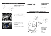
Center Speaker System
R
Designed by ALPINE Japan
Printed in Japan (S)
68P20877Y35-O
Points to Observe for Safe Usage
Points à respecter pour une utilisation sûre
Warning Avis
NE PAS TOUCHER, ENDOMMAGER OU BOU-
CHER LES TUYAUX, CONDUITES OU CABLES
LORSQUE VOUS PERCEZ DES TROUS. Il y a ris-
que d incendie, d accident ou de blessures.’ ’
ARRETEZ-VOUS IMMEDIATEMENT EN CAS DE
PROBLEME. Si un probl me se pr sente, absenceè é
du son ou de l image, objets tomb s dans l’ é ’appa-
reil, d gagement de fum e ou d odeurs nocives,é é ’
arrêtez immédiatement l’appareil et contactez le
revendeur o vous l avez achet appareil. Il y aù ’ é ’ l
risque d accident et de blessure.’
NE PAS INSTALLER L’ENCEINTE PRES DU
COUSSIN D’AIR DU PASSAGER. Si l appareil n’ ’est
pas install correctement, il risque d cher leé ’empê
fonctionnement du coussin d air, et si le coussin se’
déploie, l appareil risque d tre projet’ ’ê é dans l’habi-
tacle, causant un accident et des blessures.
NE PAS LAISSER DE PETITES PIECES A POR-
TEE DES ENFANTS. En cas d’ingestion, consul-
tez imm diatement un mé édecin.
UTILISEZ LE SYSTEME UNIQUEMENT DANS
DES VOITURES AYANT UNE MASSE NEGATIVE
(–) DE 12 VOLTS. Vérifiez avec votre revendeur
en cas de doute. Le non-respect de cette précau-
tion risque de provoquer un incendie ou un choc
électrique.
NE PAS INSTALLER DANS DES ENDROITS RIS-
QUANT DE GENER LA CONDUITE DU VEHI-
CULE OU POTENTIELLEMENT DANGEREUX
POUR LES OCCUPANTS DU VEHICULE. La vue
avant pourrait tre obstru e ou les mouvementsê é
g nê és.
NE PAS UTILISER DES ECROUS OU DES BOU-
LONS DANS LE SYSTEME DE FREINAGE PEN-
DANT L’INSTALLATION OU LES CONNEXIONS
DE MASSE. Ne jamais utiliser des pi ces liè ées à
la s crous de laécurité, telles que les boulons ou é
direction, des systèmes de freinage ou des réser-
voirs, pour faire des installations de c blage ou deâ
connexion de masse. L’utilisation de ce genre de
pièces pourrait désactiver les systèmes de con-
trôle du véhicule, endommager les freins et cau-
ser un accident ou des blessures.
CONFIEZ LE CABLAGE ET L’INSTALLATION A
DES PROFESSIONNELS. Le câblage et l’installa-
tion de cet appareil n cessitent une comp tence eté é
expérience technique confirmée. Afin de garantir la
sécurité, contactez toujours le revendeur auprès
duquel vous avez acheté l’appareil pour lui confier
les travaux faire.à
EFFECTUEZ CORRECTEMENT LES CON-
NEXIONS. Sinon il y a risque d’incendie ou d’acci-
dent.
NE PAS UT I L I SE R L’A PPARE I L DANS
D’AUTRES BUTS QUE CEUX ENONCES. Il y a
risque de choc lectrique ou de blessure.é
DO NOT CONTACT, DAMAGE OR OBSTRUCT
PIPES, FLUID LINES OR WIRING WHEN DRILL-
ING HOLES. Failure to take such precautions may
result in re or cause an accident or injuries.
HALT USE IMMEDIATELY IF A PROBLEM AP-
PEARS. When problems occur such as a lack of
sound or video, foreign objects inside the unit,
smoke coming out, or noxious odors, stop use im-
mediately and contact the dealer where you bought
the equipment. Failure to do so may result in an
accident or injury.
DO NOT INSTALL THE SPEAKER NEAR THE
PASSENGER SEAT AIR BAG. If the unit is not
installed correctly the air bag may not function cor-
rectly and when triggered the air bag may cause
the speaker to spring upwards causing an acci-
dent and injuries.
KEEP SMALL ARTICLES OUT OF THE REACH
OF CHILDREN. If swallowed, consult a physician
immediately.
USE ONLY VEHICLES WITH A 12 VOLT NEGA-
TIVE (–) GROUND. Check with your dealer if you
are not sure. Failure to do so may result in fire or
electric shock.
DO NOT INSTALL IN LOCATIONS WHICH MIGHT
HINDER VEHICLE OPERATION OR CREATE
HAZARDS FOR VEHICLE OCCUPANTS. Doing
so may obstruct forward vision or hamper move-
ment.
DO NOT USE NUTS OR BOLTS IN THE BRAKE
SYSTEM WHEN MAKING INSTALLATION OR
GROUND CONNECTIONS. Never use safety-
related parts such as bolts or nuts in the steering
or brake systems or tanks to make wiring installtions
or ground connections. Using such parts could dis-
able control of the vehicle and cause brake failure,
other accident or injury.
HAVE THE WIRING AND INSTALLATION DONE
BY EXPERTS. The wiring and installation of this
unit requires special technical skill and experience.
To ensure safety, always contact the dealer where
you purchased this unit to have the work done.
MAKE THE CORRECT CONNECTIONS. Failure
to do so may cause re or accident to occur.
DO NOT USE THIS EQUIPMENT FOR PUR-
POSES OTHER THAN STATED FOR THE VE-
HICLE. Failure to do so may result in electric shock
or injury.
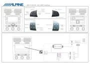
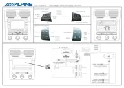
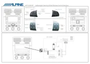
Built-in amplier
Max. power ....................................................... 35 W
Power output: RMS continuous power
(at 14.4V, 20 Hz to 20 kHz) ........................... 15.5 W
(4 ohms load, 0.08% THD)
Frequency response ....... 20 – – 20,000Hz (+0, 1dB)
S/N ratio ........................................................ 90 dBA
Input sensitivity ................................................ 0.5 V
Input impedance .................... 10 kohms (Line input)
Dimensions ................ 144(W) x 40(H) x 100(D) mm
Weight ........................................................... 0.45 kg
Power supply ...................... Operation voltage range
11 – 16V, negative ground
Speaker
System .................................. 5cm (2”) dynamic type
Power handling (Peak) ..................................... 80 W
Power handling (Continuous) .................. 20 W RMS
Impedance .................................................... 4 ohms
Sensitivity ............................................. 85 dB/W (m)
Frequency response ....................... 400 – 20,000Hz
Dimensions .................. 93(W) x 51(H) x 111(D) mm
Weight ............................................................ 0.25kg
Specifications and appearance of the product may
change without prior notice.
Toyoda Printing Co., Ltd.
4-2, Ezoe, Naka-yoshima,
Yoshima-machi, Iwaki,
Fukushima, Japan
Alpine Electronics, Inc.
Tokyo oce: 1-1-8 Nishi Gotanda,
Shinagawa-ku, Tokyo 141-8501, Japan
Tel.: (03) 3494-1101
Alpine Electronics of America, Inc.
19145 Gramercy Place, Torrance,
California 90501, U.S.A.
Tel.: 1-800-ALPINE-1 (1-800-257-4631)
Alpine Electronics of Canada, Inc.
Suite 203, 7300 Warden Ave. Markham,
Ontario L3R 9Z6, Canada
Tel.: 1-800-ALPINE-1 (1-800-257-4631)
Alpine Electronics of Australia Pty. Ltd.
6-8 Fiveways Boulevarde Keysborough,
Victoria 3173, Australia
Tel.: (03) 9769-0000
Alpine Electronics GmbH
Kreuzerkamp 7-11 40878 Ratingen,
Germany
Tel.: 02102-45 50
Alpine Italia S.p.A.
Via C. Colombo 8, 20090 Trezzano Sul
Naviglio MI, Italy
Tel.: 02-48 47 81
Alpine Electronics France S.A.R.L.
(RCS PONTOISE B 338 101 280)
98, Rue De La Belle Etoile, Z.I. Paris Nord II
B.P. 50016 F-95945, Roissy,
Charles de Gaulle Cedex, France
Tel.: 01-48 63 89 89
Alpine Electronics of U. K., Ltd.
13 Tanners Drive, Blakelands,
Milton Keynes MK14 5BU, U.K.
Tel.: 01908-61 15 56
ALPINE ELECTRONICS DE ESPAÑA, S.A.
Portal De Gamarra 36, Pabell n 32ó
01013 Vitoria (Alava) - Apdo. 133, Spain
Tel.: 34-45-283588
•Read this manual carefully before starting op-
eration and use this system safely. We cannot
be responsible for problems resulting from failure
to observe the instructions in this manual.
•This manual uses various pictorial displays to
show how to use this product safely and to avoid
harm to yourself and others and damage to your
property. Here is what these pictorial displays
mean. Understanding them is important for
reading this manual.
•Meaning of displays
This label is intended to alert the
user to the presence of important
operating instructions.
Failure to heed the instructions will
result in severe injury or death.
This label is intended to alert the
user to the presence of important
operating instructions.
Failure to heed the instructions can
result in injury or material damage.
•Lire attentivement ce manuel avant de
commencer l'op ration et l'utilisation du systé ème
en toute s . Nous d gageons touteécurité é
responsabilité des problèmes résultant du non-
respect des instructions décrites dans ce manuel.
• éCe manuel utilise divers affichages illustr s pour
montrer comment utiliser cet appareil en toute
sécurité, pour éviter de s'exposer soi-même et
les autres personnes aux dangers et pour éviter
d'endommager l'appareil. Voici la signification
de ces affichages illustr s. Il est important deé
bien les comprendre pour la lecture de ce manuel.
•Signification des affichages
Cette étiquette a pour but de
pr senceévenir l'utilisateur de la pré
d'instructions importantes.
Si ces instructions ne sont pas sui-
vies, des blessures graves ou mor-
telles risquent d' tre occasionnê ées.
Cette étiquette a pour but de
pr senceévenir l'utilisateur de la pré
d'instructions importantes.
Si ces instructions ne sont pas sui-
vies, des blessures ou des dom-
mages mat riels risquent d' tre oc-é ê
casionn s.é
Warning
Caution
DO NOT DISASSEMBLE OR ALTER. Doing so
may lead to accident, re or electric shock.
USE THE CORRECT AMPERE RATING WHEN
REPLACING FUSES. Failure to do so may result
in fire or electric shock.
BEFORE WIRING, DISCONNECT THE CABLE
FROM THE NEGATIVE (–) BATTERY TERMINAL.
Failure to do so may result in electric shock or in-
jury due to electrical shorts.
DO NOT CUT AWAY THE WIRE SHEATH AND
USE POWER FOR OTHER EQUIPMENT . Doing
so may exceed the current carrying capacity of the
wire and result in re or electric shock.
Warning Avis
Caution Attention
USE SPECIFIED ACCESSORY PARTS AND IN-
STALL THEM SECURELY. Use of other than des-
ignated parts may damage this unit internally or
may not securely install the unit in place as parts
that come loose may create hazards.
DO NOT INSTALL IN LOCATIONS WITH HIGH
MOISTURE OR DUST. A high incidence of mois-
ture or dust that penetrates into this unit may cause
smoke or fire.
DO NOT BLOCK VENTS OR RADIATOR PAN-
ELS. Blocking them may cause head to build up
inside and may result in re.
UTILISER LES ACCESSOIRES SPECIFIES ET
LES INSTALLER CORRECTEMENT. L’utilisation
d’autres pièces non d es risque de provoquerésigné
des dommages rieur de l appareil ou sonà ’ é l int ’
installation risque de ne pas tre faite correctement,ê
et les pi ces desserr es peuvent provoquer desè é
dangers.
NE PAS INSTALLER DANS DES ENDROITS TRES
HUMIDES OU POUSSIEREUX. Une humidité ou pous-
sière importante péné ’trant dans lappareil peut être à
l’ ’origine dun dégagement de fumée ou d’un incendie.
NE PAS OBSTRUER LES SORTIES D’AIR NI LES
PANNEAUX DU RADIATEUR. Une surchauffe interne
peut se produire et provoquer un incendie.
Amplificateur intégré
Puissance maximale .......................................... 35 W
Sortie de puissance: Puissance continue RMS
(à 14,4V, 20 Hz 20 kHz)à............................... 15,5 W
(4 ohms charge, 0,08% DHT)
R quence .................... 20 éponse de la fré – 20.000Hz
(+0, 1dB)–
Rapport S/N .................................................. 90 dBA
Sensibilit entré d’ ée ............................................ 0,5 V
Imp entrédance d’ ée ......... 10 kohms (Entrée de ligne)
Dimensions .................... 144(L) x 40(H) x 100(P) mm
Poids .............................................................. 0,45kg
Niveau de l’alimentation .............. Gamme de voltage de
fonctionnement 11 16V, terre n– égative
Enceinte
Système ........................... Type 5 cm (2 ) dynamique”
Charge nominale (Pointe) .................................. 80 W
Charge nominale (Continue) ..................... 20 W RMS
Impédance ..................................................... 4 ohms
Sensibilité.............................................. 85 dB/W (m)
Réponse de la fréquence .................. 400 – 20.000Hz
Dimensions ..................... 93(L) x 51(H) x 111 (P) mm
Poids .............................................................. 0,25kg
Les caract ristiques techniques et lé ’apparence du produit
peuvent changer sans préavis.
Spécifications