The icon for human
body mode” ”
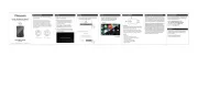
Non-Contact Forehead Thermometer
Lot label
Product label
Probe
Handle
Measurement
button
Setting buttons
Battery lid
LCD display
136
76.5 38
Resolution 0.1℃/0.1℉
Working condition
15℃~40℃(59.0℉~104℉)
RH≤95%Non-condensing
“ERR”displays when it’s not used under
working condition
Storage condition -25℃~55℃ (-13℉~131℉)
RH≤95%Non-condensing
6.Illustration
Temperature value of previous
measurement
Memory
Temperature value
Reading display
Fahrenheit reading
Celsius reading
Battery power is sufficient.
and it functions properly.
When it is
visible
Reading scale
Object mode
Human Body mode
The battery is exhausted
and thermometer can not
function properly. Please
replace battery immediately
When it
flashes
The battery is in low level,
but the thermometer is still
functional properly.Please
replace battery asap
When it is
visible
Measurement mode
Battery level
DetailsIconFunction definition
7.Display & icons
4.Features
Any object can generate certain proportion of infrared radiant energy
as per its own temperature. The radiant energy and its wavelength
distribution are subjected to its surface temperature. Based on this
principle, this thermometer is designed to detect infrared radiation
at 5~14um by highly precise infrared sensor. By adopting this high
quality sensor plus special calculation and calibration, this thermometer
is able to take accurate body temperature.
2.Working principle
3.Safety precautions
This is a Non-Contact Forehead Thermometer applicable to forehead
measurement. The thermometer measures body temperature by
collecting heat radiation emitting from forehead. New probe
structure is adopted in this thermometer. It's simply operational,
hygeian, reliable and highly accurate. Users can get precise reading
within one second by one touch. This thermometer is cost-effective
and is widely used in schools, customs, hospitals and for family use.
Intended Use & Indication for use: The Non-Contact Forehead
Thermometer is an infrared thermometer intended for the intermittent
measurement of human body temperature in people of all ages.
This thermometer is classified as a Class IIa(for CE)/class II(for FDA)
Medical Device, sorted as internally- powered equipment and type
BF application device. It's prohibited to use this thermometer in
flammable anesthetic gas or gas mixture of air and oxygen or
nitrous oxide. This is a continuous operation equipment.
1.Introduction & classification
Notice:
1.Temperature under human body mode is obtained from dynamic compensation
of environmental temp and forehead surface temp.
2. Object temperature mode is to test surface temperature of an object. The
temperature get from forehead under this mode is merely temperature of forehead
surface but not body temperature.
(fig.10.1) (fig.10.2) (fig.10.4)
5-8cm
(fig.10.3)(fig.10.5)
Press measurement button to turn on thermometer and it displays boot
screen (fig.10.1). After POST and two beeps, it will display value of last
reading and be ready for measurement (fig.10.2).
Make sure the thermometer is under body mode.
Keep distance at 5cm to 8cm from thermometer probe to the middle of
forehead (fig.10.3). Press measurement button and then it gives a beep to
indicate measurement is finished and value will be displayed (fig.10.4). If
measurement value exceeds alarm value(Defaulted value is 38℃),it gives
beep. beep. beep as a indication.
After measurement, if the thermometer is idle for 30 seconds, it will display
OFF (fig.10.5) and gives a beep and shut off automatically.
10.1 Body temperature
10.Measurement
When thermometer is on, it displays current Reading scale. Press the “C/F”button
to select reading scale.
Reading scale setting:
( fig.9.1) ( fig.9.2)
When thermometer is on, it displays current measurement
mode ( fig.9.1). Press the “Mode” button to change
measurement mode( fig.9.2).
Measurement mode setting:
User can change reading scale between Celsius and Fahrenheit, and
change measurement mode between human body mode and object
mode .
9.Setting
To switch unit of temperature readingC/F
To track last 10 readings MEM
To switch measurement mode between
human body and object
Mode
DescriptionButtons
8.Function definition of buttons
Mode MEM C/F
Power supply d.c. 3V 2*AAA Batteries
Power consumption When off≤10uW
When measurement≤30mW
Shelf life 5 Year
Memory Storage of last 10 readings
Display 3 Colors Backlight LCD (red, green, orange)
Reading scale Celsius or Fahrenheit
Automatic shut off In 30 seconds
Dimensions 136mm×76.5mm×38mm
Net weight 75g
Operating Instructions Instruction Manual
1. Take out the thermometer and open the battery
lid to install 2 *AAA batteries
2. Keep distance of 2-3 inches from thermometer
probe to the middle of forehead, please do not
contact forehead directly
3. Select measurement mode and click the
measurement button to start taking temperature
4. Reading displays on the screen after successful
measurement
2-3 IN.
Measurement button
The icon for object
mode” ”
Distinguish the positive and negative
poles of the battery
Notice:
1.
The value under this mode is object surface temperature instead of core temperature.
2.The default value of edinfrared emissivity is 0.95. The reading will deviate from the
real temperature because of different emissivity. For example, the reading on stainless
steel is obviously lower than real temperature. BE CAUTIOUS FOR SCALDING.
(fig.10.8)(fig.10.7)(fig.10.6)
Press measurement button to turn on thermometer (fig.10.6).
Make sure the thermometer is under object mode.
Keep vertical distance at 5cm to 8cm from object to measurement probe.
Press measurement button and then it gives a“beep”to indicate measurement
is finished and value will be displayed (fig.10.7).
After measurement, if the thermometer is idle for 30 seconds, it will display
“OFF”
(fig.10.8) and gives a “beep” and shut off automatically.
10.2 Object temperature
Measuring accuracy(at
laboratory conditions)
for forehead temperature:
±0.2℃/0.4℉ during 34.0℃-42.0℃;
±0.3℃/0.5℉ during 42.1℃-43.0℃.
ADIT01F
5cm~8cm (2in~3in)
Measurement
distance
Human body
Measurement
34.0℃~43.0℃ (93.2℉~109.4℉)
<34.0℃/93.2℉, “LO”displays
>43.0℃/109.4℉,“HI”displays
Object
0℃~93℃ (32.0℉~199.4℉)
<0℃/32℉,“LO”displays
>93℃/199.4℉, “HI”displays
5.Technical parameters
Warning:
Using this thermometer is not intended as a substitute for
consultation with your physician.It is dangerous for users to
perform a self-evaluation and self-treatment based on the
measuring result.please follow doctor’s instruction.
Keep the thermometer out of reach of children ,please consult
the doctor at once in case of accidental swallow of battery or
other component.
Don’t throw the battery into fire
Notice:
The device is precision instrument, don’t drop, tramp or
impose any vibration or impact on the thermometer.
Do not touch the lens of the probe with your fingers and
disassemble the device by yourself.
Please make sure your forehead is clean before measuring
forehead temperature.
Please stay still indoors about 30 minutes after exercise, eating
or bathing before measuring.
Please place the thermometer indoors for about 30 minutes if
ambient temperature varies a lot before using.
Please collect the record of Individual temperature under the
good condition of body in usual days as a reference for checking
fever or not.
Do not measure the sites of scarred tissue or tissue
compromised by skin disorders because they will affect the
accuracy of measurement.
Do not measure if patient is treated with certain drug therapies
because body temperature may rise in the drug within the effort
time limit.
Do not immerse the device into water or any other liquid, do not
expose to the sun.
Do not use a mobile or cordless hone near the thermom
measuring. Do not use the thermometer near a mobile or
cordless hone.
Please don’t measure body temperature in strong electromag-
netic interference environment (such as microwave, high
frequency equipment operation environment) to ensure the
accuracy of measurement data.
This thermometer only a personal device, please do not share
with others.
Please store the thermometer according to the technical
specifications.
Keep the sensor and probe cavity clean before use and after use.
Recommendations:
The materials (ABS) of contact with patient has passed the ISO
10993-5 and ISO 10993-10 standard test, no toxicity, allergy and
irritation reaction. They are compliant with the MDD
requirements based on the current science and technology, and
other potential allergic reactions are unknown.
The patient can measure, read data and replace battery under
normal circumstances and maintain the device and its
accessories according to the user manual.
The PATIENT is an intended OPERATOR.
Don’t use this thermometer for other purposes.
It is forbidden to leave the product exposed to any chemical
solvent, direct sunshine or high temperature in case of
damaging the product or the battery.
Do not measure while talking on the phone.
Please report to MANUFACTURER if any unexpected operation
or events occur.
Measurement mode for human body and object available,one
button to switch measurement mode;
Beeper for high temperature;
℃/℉ reading available;
Automatic shut off;
Storage of last 10 readings;
3 Colors Backlight LCD for easy reading.
Please read this manual instruction thoroughly before use.
Version: V2.0 Date: 2020-06-03
Compliant to IEC 60601-1, IEC60601-1-11, IEC 60601-1-2,
IEC 62304, ISO80601-2-56, ASTM E1965-98
Manual instruction