4
12
5 6
3
11 12 13
10
7 8 9
VE901 DisplayPort HDBaseT-Lite Extender Extensor de DisplayPort HDBaseT-Lite VE901
Extension HDBaseT-Lite DisplayPort VE901 Estensore DisplayPort HDBaseT-Lite VE901
DisplayPort-HDBaseT-Lite-Extender VE901 Удлинитель VE901 DisplayPort HDBaseT-Lite
www.aten.com www.aten.com
www.aten.com www.aten.com
www.aten.com www.aten.com
A
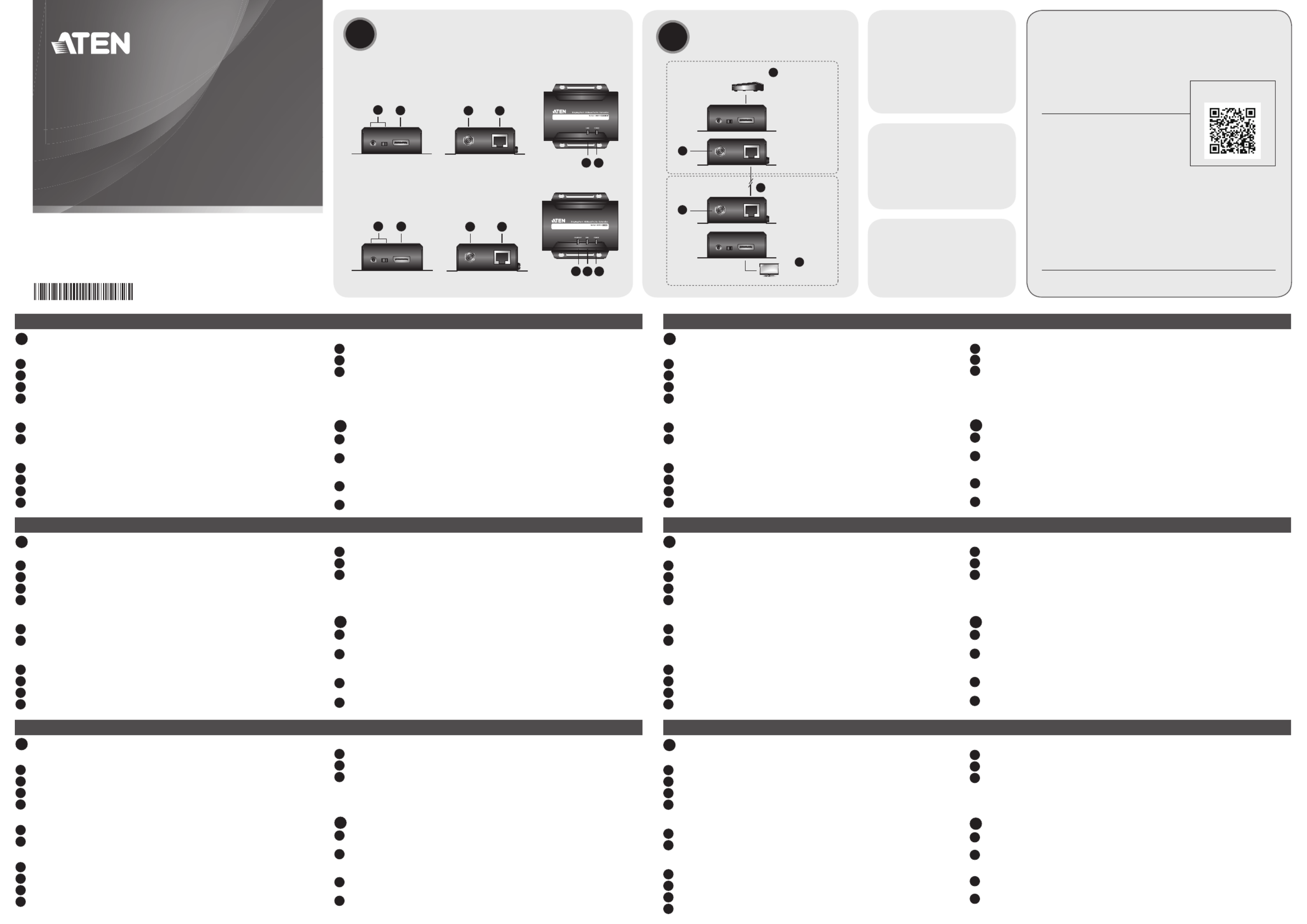
Hardware Review
VE901T Front and Rear View
1 F/W Upgrade Port and switch
2 DisplayPort Input Port
3 Power Jack
4 HDBaseT Output Port
VE901T Top View
5 Link LED
6 Power LED
VE901R Front and Rear View
7 F/W Upgrade Port and switch
8 DisplayPort Output Port
9 Power Jack
10 HDBaseT Input Port
VE901R Top View
11 Video Out LED
12 Link LED
13 Power LED
Note:
The F/W Upgrade Port is reserved for technical support. If you would like to
upgrade the fi rmware yourself, please contact your dealer.
B
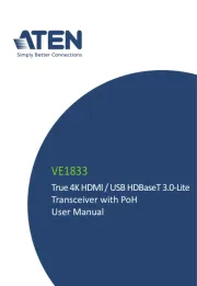
Hardware Installation
1 Connect the DisplayPort video source to the VE901T DisplayPort Input Port
with a DisplayPort cable.
2 Connect one end of the RJ-45 cable to the HDBaseT output port on the
transmitter. Then connect the other end of the RJ-45 cable to the HDBaseT
input port on the receiver.
3 Connect the VE901R DisplayPort Output Port to the DisplayPort monitor with
a DisplayPort cable.
4 Plug the power adapter cable into the power jack on both VE901 units.
AHardware Review BHardware Installation
© Copyright 2016 ATEN® International Co., Ltd.
ATEN and the ATEN logo are trademarks of ATEN International Co., Ltd. All rights reserved. All
other trademarks are the property of their respective owners.
This product is RoHS compliant.
Part No. PAPE-1223-G60G Printing Date: 10/2016
DisplayPort HDBaseT-Lite Extender
Quick Start Guide
VE901
ATEN VanCryst™
VE901 Package Contents
1 VE901T DisplayPort HDBaseT-Lite
Transmitter
1 VE901R DisplayPort HDBaseT-Lite
Receiver
2 Power Adapters
1 User Instructions
VE901T Package Contents
1 VE901T DisplayPort HDBaseT-Lite
Transmitter
1 Power Adapter
1 User Instructions
VE901R Package Contents
1 VE901R DisplayPort HDBaseT-Lite
Receiver
1 Power Adapter
1 User Instructions
DisplayPort
Source Device
VE901T
VE901R
DisplayPort Display
1
2
3
4
4
VE901T Front and Rear View
VE901R Front and Rear View
VE901T Top View
VE901R Top View
Support and Documentation Notice
All information, documentation, fi rmware, software utilities, and
specifi cations contained in this package are subject to change without
prior notifi cation bythe manufacturer.
To reduce the environmental impact of our products, ATEN
documentation and software can be found online at
http://www.aten.com/download/
Technical Support
www.aten.com/support
이 기기는 업무용(A급) 전자파적합기기로서 판매자 또는 사용자는 이 점을 주의하시기 바라며,
가정외의 지역에서 사용하는 것을 목적으로 합니다.
EMC Information
FEDERAL COMMUNICATIONS COMMISSION INTERFERENCE
STATEMENT:
This equipment has been tested and found to comply with the
limits for a Class A digital device, pursuant to Part 15 of the
FCC Rules. These limits are designed to provide reasonable
protection against harmful interference when the equipment
is operated in a commercial environment. This equipment
generates, uses, and can radiate radio frequency energy and,
if not installed and used in accordance with the instruction manual, may cause harmful interference
to radio communications. Operation of this equipment in a residential area is likely to cause harmful
interference in which case the user will be required to correct the interference at his own expense.
FCC Caution: Any changes or modifi cations not expressly approved by the party responsible for
compliance could void the user's authority to operate this equipment.
Warning: This equipment is compliant with Class A of CISPR 32. In a residential environment this
equipment may cause radio interference.
Suggestion: Shielded twisted pair (STP) cables must be used with the unit to ensure compliance with
FCC & CE standards.
This device complies with Part 15 of the FCC Rules. Operation is subject to the following two
conditions:(1) this device mat not cause harmful interference, and(2) this device must accept any
interference received, including interference that may cause undesired operation.
Scan for
more information
A
Resumen de hardware
Vista frontal y posterior del VE901T
1 Puerto de actualización del F/W y conmutador
2 Puerto de entrada DisplayPort
3 Conector de alimentación
4 Puerto de salida HDBaseT
Vista de la parte superior del VE901T
5 LED de vínculo
6 LED de alimentación
Vista frontal y posterior del VE901R
7 Puerto de actualización del F/W y conmutador
8 Puerto de salida DisplayPort
9 Conector de alimentación
10 Puerto de entrada HDBaseT
Vista de la parte superior del VE901R
11 LED de salida de vídeo
12 LED de vínculo
13 LED de alimentación
Nota:
El puerto de actualización del F/W está reservado para el soporte técnico. Si desea
realizar la actualización del fi rmware usted mismo, póngase en contacto con su
distribuidor.
B
Instalación del hardware
1 Conecte la fuente de vídeo DisplayPort al puerto de entrada DisplayPort del VE901T
con un cable DisplayPort.
2 Conecte un extremo del cable RJ-45 al puerto de salida HDBaseT en el transmisor. A
continuación, conecte el otro extremo del cable RJ-45 al puerto de entrada HDBaseT
en el receptor.
3 Conecte el puerto de salida DisplayPort del VE901R al DisplayPort del monitor con
un cable DisplayPort.
4 Conecte el cable del adaptador de alimentación en el conector de alimentación en
ambas unidades VE901.
A
Présentation du matériel
Vue de face et de dos du VE901T
1 Port et commutateur de mise à niveau du F/W
2 Port d’entrée DisplayPort
3 Fiche d'alimentation
4 Port de sortie HDBaseT
Vue de dessus du VE901T
5 LED Liaison
6 LED d'alimentation
Vue de face et de dos du VE901R
7 Port et commutateur de mise à niveau du F/W
8 Port de sortie DisplayPort
9 Fiche d'alimentation
10 Port d’entrée HDBaseT
Vue de dessus du VE901R
11 LED de sortie vidéo
12 LED Liaison
13 LED d'alimentation
Remarque :
Le port de mise à niveau du F/W est réservé à l’assistance technique. Si vous voulez
mettre à niveau le fi rmware vous-même, veuillez contacter votre revendeur.
B
Installation du matériel
1 Raccordez la source vidéo DisplayPort sur le port d’entrée DisplayPort du VE901T
avec un câble DisplayPort.
2 Branchez une extrémité du câble RJ-45 sur le port de sortie HDBaseT de l'émetteur.
Branchez ensuite l’autre extrémité du câble RJ-45 sur le port d’entrée HDBaseT du
récepteur.
3 Raccordez le port de sortie DisplayPort du VE901R au moniteur DisplayPort avec un
câble DisplayPort.
4 Branchez le câble de l'adaptateur secteur sur la prise d'alimentation des deux unités
VE901.
A
Descrizione hardware
Veduta frontale e posteriore di VE901T
1 Porta e interruttore Aggiornamento fi rmware
2 Porta input DisplayPort
3 Connettore d'alimentazione
4 Porta output HDBaseT
Veduta superiore di VE901T
5 LED collegamento
6 LED alimentazione
Veduta frontale e posteriore di VE901R
7 Porta e interruttore Aggiornamento fi rmware
8 Porta output DisplayPort
9 Connettore d'alimentazione
10 Porta input HDBaseT
Veduta superiore di VE901R
11 LED video out
12 LED collegamento
13 LED alimentazione
Nota:
La porta Aggiornamento FW è riservata all’assistenza tecnica. Contattare il rivenditore se
si vuole aggiornare il fi rmware da sé.
B
Installazione dell'hardware
1 Collegare l’origine video DisplayPort alla porta input DisplayPort di VE901T
utilizzando un cavo DisplayPort.
2 Collegare una estremità del cavo RJ-45 alla porta output HDBaseT del trasmettitore.
Quindi, collegare l’altra estremità del cavo RJ-45 alla porta input HDBaseT del
ricevitore.
3 Collegare la porta output DisplayPort di VE901R al monitor DisplayPort utilizzando
un cavo DisplayPort.
4 Collegare il cavo dell’adattatore di corrente al connettore d’alimentazione di
entrambe le unità VE901.
A
Hardwareübersicht
VE901T – Ansicht von vorne und hinten
1 Port und Schalter zur F/W-Aktualisierung
2 DisplayPort-Eingang
3 Netzanschluss
4 HDBaseT-Ausgang
VE901T – Ansicht von oben
5 Verbindung-LED
6 Betrieb-LED
VE901R – Ansicht von vorne und hinten
7 Port und Schalter zur F/W-Aktualisierung
8 DisplayPort-Ausgang
9 Netzanschluss
10 HDBaseT-Eingang
VE901R – Ansicht von oben
11 Videoausgang-LED
12 Verbindung-LED
13 Betrieb-LED
Hinweis:
Der Port zur F/W-Aktualisierung ist dem technischen Support vorbehalten. Wenden Sie
sich an Ihren Händler, falls Sie die Firmware eigenhändig aktualisieren möchten.
B
Hardwareinstallation
1 Verbinden Sie die DisplayPort-Videoquelle über ein DisplayPort-Kabel mit dem
DisplayPort-Eingang des VE901T.
2 Verbinden Sie ein Ende des RJ-45-Kabels mit dem HDBaseT-Ausgang am Sender.
Schließen Sie dann das andere Ende des RJ-45-Kabels an den HDBaseT-Eingang am
Empfänger an.
3 Verbinden Sie den DisplayPort-Ausgang des VE901R über ein DisplayPort-Kabel mit
dem DisplayPort-Monitor.
4 Schließen Sie das Netzteilkabel an den Netzanschluss an beiden VE901-Einheiten an.
A
Обзор аппаратного обеспечения
VE901T Вид спереди и сзади
1 Разъем для обновления микропрограммы и выключатель
2 Входной порт DisplayPort
3 Разъем питания
4 Выходной порт HDBaseT
VE901T Вид сверху
5 Индикатор связи
6 Индикатор питания
VE901R Вид спереди и сзади
7 Разъем для обновления микропрограммы и выключатель
8 Выходной порт DisplayPort
9 Разъем питания
10 Входной порт HDBaseT
VE901R Вид сверху
11 Индикатор видеовыхода
12 Индикатор связи
13 Индикатор питания
Примечание.
Разъем обновления микропрограммы зарезервирован для технической поддержки.
Чтобы самостоятельно выполнить обновление микропрограммы, обратитесь к продавцу.
B
Установка аппаратного обеспечения
1 Подключите источник видеосигнала DisplayPort к входному порту DisplayPort VE901T
кабелем DisplayPort.
2 Подключите другой конец кабеля RJ-45 к выходному порту HDBaseT на передатчике.
Затем подключите другой конец кабеля RJ-45 к входному порту HDBaseT на
приемнике.
3 Подключите выходной порт DisplayPort VE901R к порту DisplayPort монитора
кабелем DisplayPort.
4 Подключите сетевой шнур адаптера к разъему питания на обоих устройствах VE901.