Behringer Modamp Module 1005 Manual

Behringer Syntese maskine Modamp Module 1005

Læs gratis den danske manual til Behringer Modamp Module 1005 (4 sider) i kategorien Syntese maskine. Denne vejledning er vurderet som hjælpsom af 36 personer og har en gennemsnitlig bedømmelse på 3.8 stjerner ud af 18.5 anmeldelser. Har du et spørgsmål om Behringer Modamp Module 1005, eller vil du spørge andre brugere om produktet?

Side 1/4
Quick Start Guide
MODAMP MODULE 1005
Legendary 2500 Series Ring Modulator
and VCA Module for Eurorack
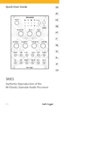
Controls
(1) AMPLIFIER GAIN – This knob controls the VCA’s gain and
nal output volume at the OUT jack.
(2) UNMOD GAIN This knob controls the IN A signal gain
when the module is in UNMOD mode (as indicated by the
UNMOD button). UNMOD mode allows the module to be
used as a VCA when modulation is not required.
(3) AMPLIFIER CONTROL MODE (EXP’L/LINEAR) –
This sliding switch determines whether the VCA gain
response is exponential (EXP’L) or linear (LINEAR).
(4) UNMOD – Press this button to place the module into
UNMOD mode. In UNMOD mode, the IN A signal passes to
the OUT jack without any modulation, and the signal level
is controlled by both the UNMOD GAIN and AMPLIFIER
GAIN knobs. IN B does not function in UNMOD mode.
(5) MOD – Press the button to activate MOD mode. In MOD
mode, the circuit combines the IN A signal and the IN B
signal to produce an output signal that is a modulated
combination of the two input signals.
(6) RATIO – Use this knob in MOD mode to oset the tune
control voltage that is sent out through the CV B jack.
This function only operates when MOD mode is selected.
(7) TUNE – Use this knob in MOD mode to control the output
level of the tune control voltage sent out through both
the CV A and CV B jacks. This function only operates when
MOD mode is selected.
(8) IN A – This knob controls the input level for the signal
coming in through the IN A jack.
(9) IN B – This knob controls the input level for the signal
coming in through the IN B jack.
(10) IN A / IN B – Use these input jacks to route in audio
signals for the internal modulation process via cables with
3.5 mm connectors.
(11) CV A / CV B – Use these jacks to route TUNE (CV A and
CV B) and RATIO (CV B oset) control voltages out to the
two VCOs that typically supply the audio signals to the IN A
and IN B inputs to be modulated.
(12) CV IN – Use this jack to route in control voltage signals for
remote control of the AMPLIFIER GAIN setting.
(13) MOD – Use this jack to route in a trigger signal to remotely
activate MOD mode via a cable with 3.5 mm connectors.
(14) GATE – Use this input jack to route in a gate signal to
turn the modulation circuit on and o via a cable with
3.5 mm connectors.
(15) UNMOD – Use this jack to route in a trigger signal to
remotely switch o MOD mode via a cable with 3.5 mm
connectors .
(16) OUT This jack sends out the nal VCA signal via cable
with 3.5 mm connectors.
(1)
(2) (3)
(4) (5)
(6)
(7) (8)
(9)
(10)
(11)
(12)
(13)
(14) (15) (16)
V 1.0
Power Connection
The MODAMP MODULE 1005 module comes with the required
power cable for connecting to a standard Eurorack power supply
system. Follow these steps to connect power to the module.
It is easier to make these connections before the module has been
mounted into a rack case.
1. Turn the power supply or rack case power o and
disconnect the power cable.
2. Insert the 16-pin connector on the power cable into the
socket on the power supply or rack case. The connector has
a tab that will align with the gap in the socket, so it cannot
be inserted incorrectly. If the power supply does not have
a keyed socket, be sure to orient pin 1 (-12 V) with the red
stripe on the cable.
3. Insert the 10-pin connector into the socket on the back of
the module. The connector has a tab that will align with the
socket for correct orientation.
4. After both ends of the power cable have been securely
attached, you may mount the module in a case and turn on
the power supply.
Installation
The necessary screws are included with the module for mounting in
a Eurorack case. Connect the power cable before mounting.
Depending on the rack case, there may be a series of xed holes
spaced 2 HP apart along the length of the case, or a track that allows
individual threaded plates to slide along the length of the case.
The free-moving threaded plates allow precise positioning of the
module, but each plate should be positioned in the approximate
relation to the mounting holes in your module before attaching
the screws.
Hold the module against the Eurorack rails so that each of the
mounting holes are aligned with a threaded rail or threaded
plate. Attach the screws part way to start, which will allow
small adjustments to the positioning while you get them all
aligned. After the nal position has been established, tighten the
screws down.
2MODAMP MODULE 1005


Produkt Specifikationer

Mærke: Behringer
Kategori: Syntese maskine
Model: Modamp Module 1005

Har du brug for hjælp?

Hvis du har brug for hjælp til Behringer Modamp Module 1005 stil et spørgsmål nedenfor, og andre brugere vil svare dig


Syntese maskine Behringer Manualer

Syntese maskine Manualer

Nyeste Syntese maskine Manualer