Systemwächter-Leistungsteil REG - 1-
Kanal, 2-Kanal
Sicherheitshinweise
Einbau und Montage elektrischer Geräte dürfen
nur durch Elektrofachkräfte erfolgen.
Bei Nichtbeachten der Anleitung können
Schäden am Gerät, Brand oder andere Gefahren
entstehen.
Gefahr durch elektrischen Schlag. Gerät ist nicht
zum Freischalten geeignet.
Gefahr durch elektrischen Schlag. Vor Arbeiten
an Gerät oder Last freischalten. Dabei alle
Leitungsschutzschalter berücksichtigen, die
gefährliche Spannungen an Gerät oder Last
liefern.
Diese Anleitung ist Bestandteil des Produktes
und muss beim Endkunden verbleiben.
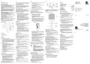
Geräteaufbau
System-Leistungsteil 1-Kanal REG
Bild 1: Leistungsteil 1-Kanal
(1) Status LED
(2) Einsteller Nachlaufzeit, MIN
(3) Einsteller Helligkeitsschwelle, LUX
(4) Einsteller Zwangsabschaltung, LIMIT
(5) Klemme Lx Helligkeitsauswertung vom System-
Sensor
(6) Klemme S Signalauswertung vom System-
Sensor
(7) Klemmen 1 und 4 potentialfreier Schaltkontakt
System-Leistungsteil 2-Kanal REG
Bild 2: Leistungsteil 2-Kanal
(8) Schaltkontakt Kanal 1
(9) Schaltkontakt Kanal 2
(10) Kanal 1: Status LED und Einsteller für MIN, LUX
und LIMIT
(11) Kanal 2: Status LED und Einsteller für MIN, LUX
und LIMIT
(12) Anschluss System-Sensoren für Kanal 1
(13) Anschluss System-Sensoren für Kanal 2
Funktion
Bestimmungsgemäßer Gebrauch
- Schalten von elektrischen Lasten für die Dauer
einer einstellbaren Zeit bei unterschrittener
Helligkeitsschwelle
- Betrieb mit geeigneten System-Sensoren
- Einbau in Unterverteiler auf Hutschiene nach
DIN EN 60715
Produkteigenschaften
System-Leistungsteil 1-Kanal REG
- Gerät reagiert auf Bewegungserkennung von
System-Sensoren
- Helligkeitsschwelle einstellbar
- Einschaltdauer einstellbar
- Zwangsabschaltung einstellbar, Limitfunktion
- Potentialfreier Schließerkontakt
- Kleinspannung schaltbar
- Manuelles Einschalten mit Installationstaster,
Öffner möglich
System-Leistungsteil 2-Kanal REG
- Gerät reagiert auf Bewegungserkennung von
System-Sensoren
- Helligkeitsschwelle für beide Kanäle separat
einstellbar
- Einschaltdauer für beide Kanäle separat
einstellbar
- Zwangsabschaltung für beide Kanäle separat
einstellbar
- Kanal 1: Potentialbehafteter Schließerkontakt
- Kanal 2: Potentialfreier Schließerkontakt
- Manuelles Einschalten beider Kanäle
gemeinsam mit Installationstaster, Öffner
möglich
Automatikbetrieb
System-Sensoren (Zubehör) erfassen
Wärmebewegungen von Personen, Tieren oder
Gegenständen und geben Bewegungssignale und
den aktuellen Helligkeitswert an das Leistungsteil
weiter.
- Das Licht wird eingeschaltet, wenn der
überwachte Erfassungsbereich betreten wird
und die eingestellte Helligkeitsschwelle
unterschritten ist.
- Das Licht wird ausgeschaltet, wenn im
Erfassungsbereich keine Bewegung mehr
erfasst wird und die Nachlaufzeit abgelaufen ist.
Zur Vermeidung von Lichtschaukeln durch ein
abkühlendes Leuchtmittel wertet das Leistungsteil
nach dem Ausschalten für ca. 3 Sekunden keine
Signale aus.
Durch Einschalten der Netzspannung wird ein
Schaltvorgang des Leistungsteils ausgelöst.
Die Status-LED (1) des jeweiligen Kanals leuchtet,
wenn die Last eingeschaltet ist.
Bedienung
Licht manuell einschalten
Optionaler Installationstaster, Öffner ist installiert
(Montage und elektrischer Anschluss).
o Installationstaster mindestens 1 Sekunde
drücken.
Licht wird helligkeitsunabhängig für die
eingestellte Nachlaufzeit eingeschaltet.
Erkannte Bewegungen starten die Nachlaufzeit
neu.
Leistungsteil konfigurieren
Mit drei Einstellern kann die Nachlaufzeit, die
Helligkeitsschwelle und bei Bedarf eine
Zwangsabschaltung nach 90 Minuten eingestellt
werden.
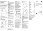
Bild 3: Einsteller Leistungsteil
Nachlaufzeit einstellen
Für diese Zeitdauer bleibt das Licht ab der letzten
Bewegungserkennung eingeschaltet. Die
Nachlaufzeit wird zwischen ca. 4 Sekunden und
15 Minuten eingestellt.
o Einsteller MIN (2) in gewünschte Position
drehen (Bild 3).
Helligkeitsschwelle einstellen
Die Helligkeitsschwelle wird zwischen ca. 3 und
80 Lux oder Tagbetrieb eingestellt.
o Einsteller LUX (3) in gewünschte Position
drehen (Bild 3). Eine Einstellung auf ca. 10 Lux
aktiviert das Gerät bei Dämmerungsbeginn. Für
helligkeitsunabhängiges Schalten den Einsteller
bis Rechtsanschlag drehen.
Zwangsabschaltung einschalten
Mit dem Einsteller LIMIT (4) kann eine
Zwangsabschaltung eingeschaltet 90 MIN oder
abgeschaltet OFF werden. Bei aktiver
Zwangsabschaltung schaltet das Leistungsteil nach
spätestens 90 Minuten ab. Ein Wiedereinschalten
erfolgt nur, wenn die Helligkeitsschwelle
unterschritten ist und erneut Bewegung im
Erfassungsbereich erkannt wird. Die
Zwangsabschaltung verhindert, dass bei ständiger
Bewegungserkennung das Licht nicht ausschaltet,
auch wenn es hell genug ist.
o Einsteller LIMIT auf 90 MIN einstellen.
Informationen für Elektrofachkräfte
Montage und elektrischer Anschluss
GEFAHR!
Elektrischer Schlag bei Berühren
spannungsführender Teile.
Elektrischer Schlag kann zum Tod
führen.
Vor Arbeiten an Gerät oder Last alle
zugehörigen Leitungsschutzschalter
freischalten. Spannungsführende Teile
in der Umgebung abdecken!
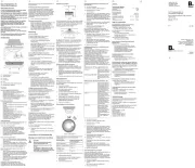
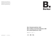
Leistungsteil 1-Kanal anschließen und montieren
Bild 4: Anschlussplan Leistungsteil 1-Kanal
o Leistungsteil auf Hutschiene montieren.
o Leistungsteil gemäß Anschlussplan (Bild 4)
anschließen. Optional Installationstaster T,
Öffner in die Zuleitung des Leistungsteils
einfügen, um das Leistungsteil auch manuell für
die Dauer der Nachlaufzeit einschalten zu
können.
o Brücke zwischen Klemmen L
1
und 4 bei
Anschluss des Schaltkontaktes am gleichen
Außenleiter installieren.
i Der Schaltausgang kann an einem anderen
Außenleiter als die Versorgungsspannung
betrieben werden.
o Liefern mehrere Leitungsschutzschalter
gefährliche Spannungen an Gerät oder Last, die
Leitungsschutzschalter koppeln oder mit einem
Warnhinweis so beschriften, dass ein
Freischalten sichergestellt ist.
o System-Sensoren an die Klemmen Lx, S, - und
+ des Leistungsteils anschließen (siehe
Anleitung System-Sensoren).
Mit Leistungsteil 1-Kanal Kleinspannung
schalten
Bild 5: Anschlussplan Schaltkontakt an
Kleinspannung
o Leistungsteil gemäß Anschlussplan (Bild 5)
anschließen.
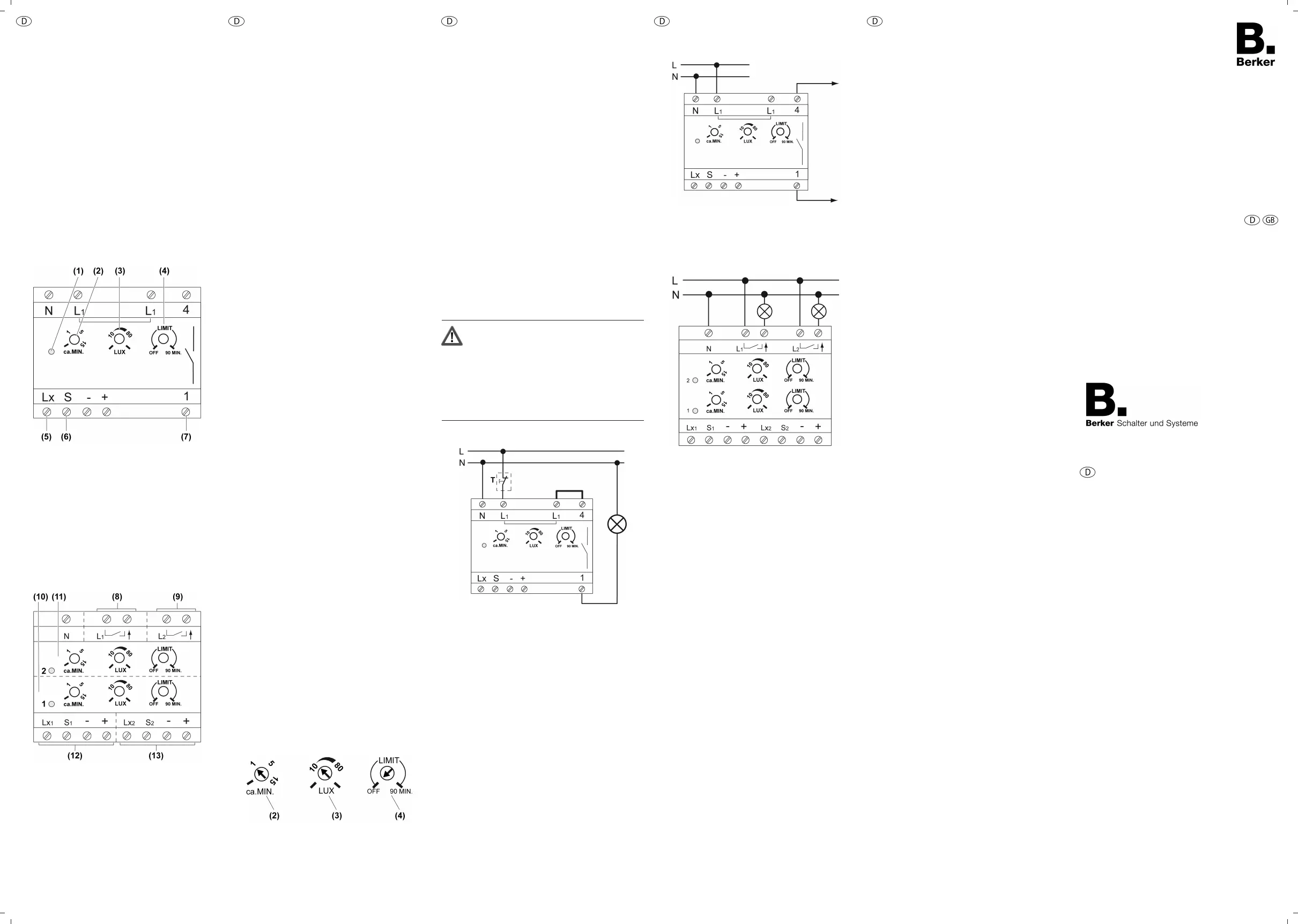
Leistungsteil 2-Kanal anschließen und montieren
Bild 6: Anschlussplan Leistungsteil 2-Kanal
o Leistungsteil auf Hutschiene montieren.
o Leistungsteil gemäß Anschlussplan (Bild 6)
anschließen.
o Liefern mehrere Leitungsschutzschalter
gefährliche Spannungen an Gerät oder Last, die
Leitungsschutzschalter koppeln oder mit einem
Warnhinweis so beschriften, dass ein
Freischalten sichergestellt ist.
o System-Sensoren an die Klemmen Lx, S, - und
+ des Leistungsteils für Kanal 1 und 2
anschließen (siehe Anleitung System-
Sensoren).
i Die beiden Schaltausgänge L
1
und L
2
können an
unterschiedlichen Außenleitern betrieben
werden.
i Werden mehr als 8 System-Sensoren benötigt,
müssen die Ausgänge von Kanal 1 und Kanal 2
parallel geschaltet werden. Dazu ist eine Brücke
zwischen Ausgang 1 und Ausgang 2 zu legen.
Die maximale Anschlussleistung erhöht sich
dabei nicht.
i Parallelschalten mehrerer Leistungsteile ist
ausgangsseitig möglich, allerdings erhöht sich
dabei die maximale Anschlussleistung nicht.
Inbetriebnahme
Wächtersystem in Betrieb nehmen
o System-Sensoren nacheinander anschließen
(siehe Anleitung System-Sensoren) und einzeln
prüfen, um die Funktion sicherzustellen.
o Leistungsteil für die Funktionsprüfung der
Sensoren folgendermaßen einstellen:
Einsteller MIN ca. 4 Sekunden, Linksanschlag
Einsteller LUX Tagbetrieb, Rechtsanschlag
o Erfassungsbereich für jeden System-Sensor
einzeln abschreiten, dabei auf sichere Erfassung
und Störquellen achten (siehe Anleitung
System-Sensoren).
o Nach der Inbetriebnahme der System-Sensoren
die Einsteller MIN, LUX und LIMIT für den
Normalbetrieb einstellen.
Anhang
Technische Daten
Nennspannung AC 230 V ~
Netzfrequenz 50 Hz
Leistungsaufnahme
Best.-Nr. 155 ca. 1,1W
Best.-Nr. 159 ca. 1,8W
Umgebungstemperatur -25 ... +55 °C
Nachlaufzeit ca. 4 s ... 15 min
Helligkeitseinstellung ca. 3 ... 80 lx (und
Tagbetrieb)
Anschlussleistung bei AC 230 V ~
Glühlampen 2300 W
HV-Halogenlampen 2300 W
Tronic-Trafos 1200 W
Induktive Trafos 1200 VA
EVG typabhängig
Leuchtstofflampen
unkompensiert
1200 VA
Leuchtstofflampen
parallelkompensiert
920 VA
Leuchtstofflampen Duo-
Schaltung
2300 VA
Schaltstrom 10 A
Einschaltstrom max. 20 A je Kanal
Mindestschaltstrom 100 mA
Mindestschaltspannung AC 12 V~
Kontaktart µ
Anschluss
eindrähtig 1,5 ... 4 mm²
feindrähtig ohne
Aderendhülse
0,75 ... 4 mm²
feindrähtig mit
Aderendhülse
0,5 ... 2,5 mm²
Anzahl System-Sensoren max. 8 (je Kanal)
Gesamtlänge Lastleitung max. 100 m
Einbaubreite 72 mm / 4 TE
Zubehör
Systemwächter 180° AP Best.-Nr. 151 09
Systemwächter 240° AP Best.-Nr. 152 09
Gewährleistung
Technische und formale Änderungen am Produkt,
soweit sie dem technischen Fortschritt dienen,
behalten wir uns vor.
Wir leisten Gewähr im Rahmen der gesetzlichen
Bestimmungen.
Im Gewährleistungsfall bitte an die Verkaufsstelle
wenden oder das Gerät portofrei mit
Fehlerbeschreibung an unser Service-Center
senden.
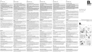
Berker GmbH & Co. KG
Service-Center
Hubertusstraße 17
D-57482 Wenden-Ottfingen
Telefon: 0 23 55 / 90 5-0
Telefax: 0 23 55 / 90 5-111
24.09.2013
82508311
97-09475-000
Systemwächter-Leistungsteil REG - 1-
Kanal, 2-Kanal
System motion detector power RMD -
1-channel, 2-channel
Best.-Nr. /Order No.
155, 159
Berker GmbH & Co. KG
Klagebach 38
58579 Schalksmühle/Germany
Telefon + 49 (0) 2355/905-0
Telefax + 49 (0) 2355/905-111
www.berker.de
Bedienungs- und
Montageanleitung
Operation- and
Assembly Instructions