04/2022
6LE005209C
IR motion detector comfort 1.1 m
Order no.: 8534 12 ..
IR motion detector comfort 2.2 m
Order no.: 8534 22 ..
Operating and assembly
instructions
Berker GmbH & Co. KG
Zum Gunterstal
66440 Blieskastel, Germany
Tel.: + 49 6842 945 0
Fax: + 49 6842 945 4625
e-mail: info@berker.de
www.berker.com
z
IR motion detector comfort 1.1 m / 2.2 m
Safety instructions
Electrical equipment must only be installed and
assembled by a qualied electrician in accord-
ance with the relevant installation standards,
regulations, directives and safety and accident
prevention directives of the country.
Failure to comply with these installation instruc-
tions may result in damage to the device, re or
other hazards.
Due to its detection behaviour the device is not
suitable for use in burglary detection or alarm
systems.
These instructions are an integral component of
the product and must be retained by the end user.
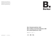
Design and layout of the device
(3)
(5)
(6)
(4)
(2)
(1)
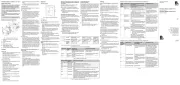
Fig. 1: Design and layout of the device
(1) Insert (see "Accessories", not in scope of
delivery)
(2) Frame (not included)
(3) cover
(4) Motion detector design cover
(5) Module retaining screw
(not for Berker R.1/R.3/R.8)
(6) Interface between insert/application module
Function
Correct use
- Automatic switching of lighting depending on heat
motion and ambient brightness
- Application module for switch insert, dimmer in-
sert or motion detector extension unit
- Only suitable for use in indoor areas with no drip
and no spray water.
Product characteristics
- Integrated button for selecting operating modes
and special functions
- Lockable integrated button
- Operating mode - automatic mode, permanent
ON, permanent OFF can be selected
- Display operating mode via LED
- Potentiometer for setting the response bright-
ness, delay time and detection sensitivity
- Delay time adjustable
- Pulse encoder mode for current pulse/stairwell
circuits
- Adjustable detection angle for adapting the de-
tection area
- Additional adjustment of the response brightness
via Teach-In function
- Party function
- Presence simulation
- Operation on motion detector extension units
- Optional extension unit operation via installation
button
- Commissioning optionally via IR remote control
for comfort motion detector (see accessories)
Automatic mode
The motion detector detects heat motion caused by
people, animals, or objects.
On switch insert:
- The light will be switched on for the delay time, if
movements are detected in the detection area
and the set brightness threshold is undershot.
Each detected movement restarts the delay time.
- The light will be switched o if no additional
movements are detected in the detection area
and the set delay time has elapsed.
On dimmer insert:
- The light will be switched on to the switch-on
brightness level for the delay time if movements
are detected in the detection area and the set
brightness threshold is undershot. Each detected
movement restarts the delay time.
- After the delay time elapses the lighting will be
dimmed to 50% of the switch-on brightness-level
and will remain at this brightness level for 30 s
(switch-o pre-warning). Any motion detected
during the switch-o pre-warning restarts the de-
lay time and restores the switch-on brightness
level.
- The light will be switched o if no motion is de-
tected any longer in the detection area and the
set delay time and the switch-o time have
elapsed.
On extension unit
- If motion is detected in the detection area of the
extension unit, the extension unit insert sends a
pulse to the main unit and then locks for 10 sec-
onds. Recording takes place independently of the
brightness on the extension unit. If motion is still
detected after 10 seconds, a pulse is sent again.
- Upon receiving an extension unit pulse, the main
unit switches the light on for the delay time, if the
set brightness threshold is undershot. Every fur-
ther extension unit pulse restarts the delay time
of the main unit.
Performance after mains breakdown/return of
mains supply
- Mains breakdown shorter than 0.2 s:
The function is not impaired.
- Mains breakdown longer than 0.2 s:
There is no function during the mains breakdown.
The current conguration is saved in non-volatile
memory.
- Return of mains supply:
The application module executes an initialisation
for approx. 15 s, during which the lighting will be
switched on. Motion detection starts thereafter. If
no motion is detected during the rst 5 s, the
lighting is switched o. The saved conguration is
loaded from memory. During this period local op-
eration via the button or extension unit can be
used.
Operation
Operating concept
(8)
(7)
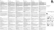
Fig. 2: Operation and display elements
(7) Button
(8) Status LED
Operation is executed by pushing the button (7) on
the motion detector:
- A short press of the button switches the operating
modes. The operating mode is displayed via the
status LED behind the optics cover of the motion
detector.
- Keeping the button pressed activates special
functions. Selection of the special functions is
supported by the LED display (Fig. 3).
Selecting the operating mode
Briey press the button repeatedly until the de-
sired operating mode is selected.
The status LED indicates the selected operating
mode (see Table 1).
Switching the operating mode nishes the party
function or presence simulation, if these functions
were previously active.
Disabling/enabling operating mode selection via
button
Keep the button pressed for more than 15
seconds, until the status LED is ashing green
(Fig. 3).
Selection of the operating mode via the button is
disabled.
or if the button is locked:
Keep the button pressed for more than 15
seconds, until the status LED is ashing green
(Fig. 3).
The operating mode can be selected via the
button again.
Switching on the lighting via push-button exten-
sion unit or changing the switch-on brightness
level (Table 2)
Optionally the lighting can be switched on via a
mechanical push-button extension unit.
For extension unit operation, the lighting is
switched on independently of the set brightness
threshold.
When using the dimmer inserts, the last set
brightness level will be saved as the switch-on
brightness-level.
Activating/interrupting party function
The party function switches the lighting on for 2
hours. During this time no extension unit commands
are executed.
In the case of motion detectors on extensions,
activating the party function causes cyclical trans-
mission of the switch-on pulse every 10 s. How-
ever, the light is only switched on when the
brightness threshold is undershot at the main
unit.
Keep the button pressed for more than 5 sec-
onds, until the status LED is ashing red (Fig. 3).
The lighting is switched on for 2 hours. During
this time the status LED is ashing red. Upon
elapse of 2 hours, the motion detector switches
to Autooperation mode.
Briey press the button.
The party function will be cancelled, the motion
detector returns to Auto operation mode.
Activating/deactivating
presence simulation
During operation, the motion detector counts the mo-
tion detections in one full hour and saves the result.
With active presence simulation at the beginning of
the hour with the most detections saved, the light
will be switched on for the duration of the delay time,
even no motion is detected.
During the presence simulation, presence detection
and extension unit commands will continue to be
executed normally.
The presence simulation cannot be activated via
the extension unit
Keep the button pressed for more than 20 sec-
onds, until the status LED is slowly ashing red
(gure 3).
The presence simulation is active. During this
time the status LED lights orange. The motion
detector switches the lighting on at the saved
time.
Briey press the button.
The presence simulation will be disabled, the
motion detector returns to Automode.
Settings
Setting response brightness via Teach-In func-
tion
The response brightness is the brightness value
saved in the motion detector; when this value is
undershot the motion detector switches the connect-
ed load if movements are detected. Via Teach-In
function the current ambient brightness is saved as
the response brightness.
Teach-In cannot be carried out on the extension
unit.
The load is switched o.
Keep the button pressed for more than 10
seconds, until the status LED is ashing orange
(Fig. 3).
The motion detector detects the current ambient
brightness and saves it as response brightness.
Setting of the response brightness via Teach-In
function and via the brightness potentiometer has
the same priority. Teach-In overwrites the re-
sponse brightness set on the brightness potenti-
ometer. If the setting is made again via the poten-
tiometer , the Teach-In gure will be overwritten.
Setting the load
If the switching performance is not satisfactory after
commissioning when using the motion detector on
universal switch inserts and universal touch dim-
mers, a load setting must be carried out.
A load setting is required each time the load is
changed.
Switch o load.
Keep the button pressed for more than 25
seconds, until the status LED is slowly ashing
orange.
Release push-button.
The connected load blinks once. The device is in
selection mode.
If no further actions are performed within the next
10 seconds, the dimmer switches to normal oper-
ation.
Briey press the bottom button repeatedly to
activate the desired setting mode.
► See Table 3a / 3b
Information for electricians:
For the version labelling of the ush-mounted
insert, see packaging label or sticker on the back
of the housing.
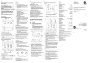
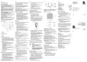
Function Party function Teach-In Keylock Presence
simulation
Load setting
mode
1)
LED display
red
orange green red orange
Hold time
operation
button
> 5 s > 10 s > 15 s > 20 s > 25 s
1)
Only on universal switch insert and universal dimmer insert
Fig. 3: Selection of special functions and LED display
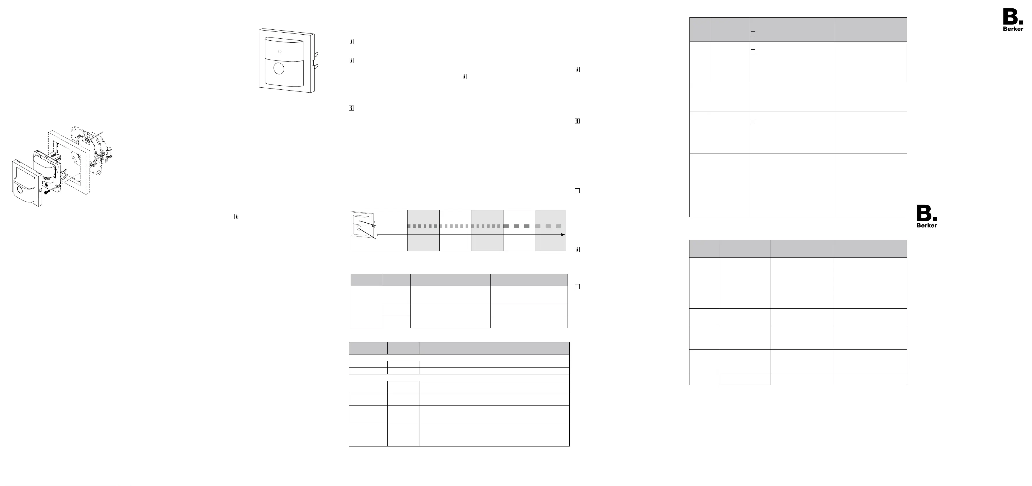
LED display Operating
mode
On switch or
dimmer insert
On extension unit insert
-- Auto Motion-dependent and brightness-
dependent switch on/switch o of
the load
Motion-independent switching pulse
for the main unit
green Permanent
ON
Load is permanently switched-on/
switched-o.
Extension unit signals will not be
evaluated
Cyclical transmission of the switch-
on pulse every 10 s
red Permanent
OFF
--
Table 1: Display of operating modes
Dimming status Operation
button
Performance of the insert
Motion detector applied on switch insert
OFF Short press Load is switched on for the set delay time
ON Short press Extension of switch-on time by the set delay time
Motion detector applied on push-button dimmer comfort 1gang
OFF Short press Load is switched on to the switch-on brightness-level for the set delay
time
ON Short press Extension of switch-on time by the set delay time at the same
brightness
OFF Long press Load is switched on to switch-on brightness-level, subsequent dimming
in the opposite direction of the last dimming process. Thereafter the
load remains switched on for the delay time
ON Long press Changes the current brightness. Dimming takes place in the opposite
direction of the last dimming operation until maximum or minimum
brightness. Subsequently the load remains switched on at the set
brightness for the set delay time.
Table 2: Operation via push-button extension unit
Setting the load on a universal switch or dimmer insert from Version R1.2
Briey
press
the
button
Setting mode Duration and conrmation of the
load setting
The light to conrm the load ashes at
50% brightness.
Information for use
1 x Load
factory setting
Settings duration: approx. 30 sec.
Load switching/dimming phases may
occur during the automatic settings
process.
The load ashes one last time as a con-
rmation and then goes out. The device
returns to normal operation.
Factory setting with automatic
load recognition.
If the switching behaviour is
unsatisfactory after that, restart
selection mode and select the
best option.
2 x LED mode 1
(phase cut-on)
After approx. 5 sec., the load ashes
twice as a conrmation and then goes
out. The device returns to normal oper-
ation.
Recommended for lower 230 V
LED loads up to max. 60 W if the
switching/dimming behaviour is
unsatisfactory after automatic
load setting.
3 x LED mode 2
(phase cut-on)
Settings duration: ≤ 50 sec.
Load switching/dimming phases may
occur during the automatic settings
process.
Finally, the load ashes three times as
a conrmation and then goes out. The
device returns to normal operation.
Recommended for higher 230 V
LED loads from 50 W, which can
be operated in the phase cut-on.
Observe manufacturer's data!
4 x Fine setting of
minimum bright-
ness
5 predened minimum brightness levels
for 2.5 sec. each, run through repeated-
ly (3 runs).
As soon as the connected load
shows a satisfactory minimum bright-
ness, conrm by quickly pressing the
bottom button.
After approx. 5 sec., the load ashes
four times as a conrmation and re-
mains switched on (50% brightness).
The device returns to normal operation.
To optimise the switch-on behav-
iour, or if the load ickers in the
lower dimming range, the mini-
mum brightness setting can be
manually adjusted here.
Table 3a
Setting the load on a universal switch or dimmer insert up to Version R1.1
Briey
press the
button
Setting mode Conrmation of the
load setting
Information for use
1 x Load ne-setting Load blinks 1 x after approx.
30 s and changes to normal
operation
Not suitable for ohmic loads
(e.g. incandescent, HV halogen
lamps); use factory load setting.
If the load ne-setting does
not bring any improvement for
energy-saving lamps or 230 V
LED lamps, select the energy-
saving lamp ne-setting or 230 V
LED lamp universal setting.
2 x Factory load setting Load blinks 2 x after approx.
6 s and changes to normal
operation
3 x Energy-saving lamp
ne-setting in phase
cut-on
Load blinks 3 x after approx.
30 s and changes to normal
operation
Energy-saving lamps are
switched on at a brightness level
of at least 50% in order to ensure
an ignition process.
4 x 230 V LED lamp uni-
versal setting in phase
cut-on or phase cut-o
Load blinks 4 x after approx.
5 s and changes to normal
operation
For connected dimmable 230 V
LED lamps the dimming principle
and the optimal switch-on bright-
ness level is set automatically.
For all setting modes Load blinks 5 x The selected setting mode is not
supported by the insert.
Table 3b