BlaknBlu Foxtrot Manual


Læs gratis den danske manual til BlaknBlu Foxtrot (4 sider) i kategorien Ikke kategoriseret. Denne vejledning er vurderet som hjælpsom af 2 personer og har en gennemsnitlig bedømmelse på 4.8 stjerner ud af 1.5 anmeldelser. Har du et spørgsmål om BlaknBlu Foxtrot, eller vil du spørge andre brugere om produktet?

Side 1/4
of 1 4
Foxtrot User Manual
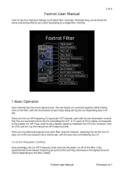
Foxtrot has four identical Voltage Controlled Filter channels. Although they can be linked for
some interesting effects, let’s start by looking at a single filter channel.
1. Basic Operation
Each channel has two mono signal inputs. The two inputs are summed together before being
sent to the filter, with the attenuation of each input being set by the corresponding input trim
There are two cut off frequency CV inputs per VCF channel, each with its own attenuator control.
The CVs are summed to form the CV controlling the VCF. A CV input of 0V or below corresponds
to the lowest cut-off. If you want to use a bipolar signal to modulate the VCFs (for instance, from
an LFO), just turn up the manual cut off frequency knob.
There are two identical outputs from each filter channel, however, selecting Pan as the Aux CV
input turns the two outputs into a stereo pair, with the pan now controlled by Aux CV.
1.1 CUT OFF FREQUENCY CONTROL
Unsurprisingly, the Cut Off Frequency knob controls the static cut off of the filter. Fully
anticlockwise is the lowest frequency (around 20Hz) and fully clockwise is the highest (around
20kHz depending on the filter model).
Foxtrot User Manual
Firmware v2.1
Signal Inputs
Boost/Overdrive
Filter Link
Filter Model
Signal Input Attenuators
Clipping
Dual/Stereo Outputs
Aux CV Select
Aux CV Input Attenuator
Cut-off CV Input Attenuators
Aux CV Input
Cut-off CV Inputs
Foxtrot Filter
Foxtrot Filter
Foxtrot Filter
Foxtrot FilterFoxtrot Filter
of 2 4
1.2 FILTER TYPE SWITCH
Each Foxtrot channel has a choice of three virtual analog filter models.
Setting the Filter Type switch to LD selects a Moog style 4th order ladder filter.
The SK setting selects a 2nd order ‘Sallen-and-Key’ filter based on the Korg 35 analog module
used in early Korg synthesizers.
SV is a State Variable filter similar to the Oberheim SEM filter.
1.3 BP<-LP->HP CONTROL
Each filter type can be continuously varied from Band Pass through Low Pass to High Pass
using this control, extending the capabilities of the original analog designs on which the Foxtrot
filters are based.
There is a detent at the LP position so that you can be sure the response is truly just low pass.
As with the Oberheim SEM, a setting half way between Low Pass and High Pass gives you a
notch filter.
1.4 RESONANCE CONTROL
This controls the filter Resonance – sometimes called Q, Peak, or Emphasis. At high Resonance
settings, the LD and SK filters will self-oscillate. The SK filter is particularly keen!
1.5 BOOST SWITCH
The classic analog filter designs that Foxtrot models have various sources of non-linearity – in !
other words, bits of circuit that don’t behave perfectly, introducing distortion to the audio signal.
The Moog ladder filter has gentle distortion in each of its ladder ‘rungs’. The Korg design actually
has a diode based clipper – similar to the circuit in guitar fuzz pedals. Much of the character of !
the filters come from these imperfections.
Foxtrot accurately mimics these non-linearities and includes a Boost switch, to overdrive the
filters for even more distortion. Note that overdriving filters tends to decrease the effect of
resonance. Foxtrot compensates for this effect (to some degree) by increasing the maximum
resonance when Boost is enabled.
1.6 CLIPPING LED
With high audio input levels – particularly if you are using both inputs – and with some filter ! !
settings, it’s possible for the filter to exceed the output level possible in Eurorack, so a soft-
clipping circuit is included in each output. When the circuit is active, the Clipping LED illuminates.
Unless you like the effect (!) you can reduce the clipping by turning down the audio inputs using
the attenuator knobs.
1.6 AUX CV MODE SWITCH
The AUX CV input can be selected to control one of three filter functions.
When set to MIX the AUX CV controls the sweep from band pass to low pass to high pass. A 0V
CV input corresponds to low pass, negative CVs sweep the response towards band pass,
Foxtrot User Manual
Firmware v2.1


Produkt Specifikationer

Mærke: BlaknBlu
Kategori: Ikke kategoriseret
Model: Foxtrot

Har du brug for hjælp?

Hvis du har brug for hjælp til BlaknBlu Foxtrot stil et spørgsmål nedenfor, og andre brugere vil svare dig


Ikke kategoriseret BlaknBlu Manualer

BlaknBlu

BlaknBlu Foxtrot Manual

10 Marts 2025

Ikke kategoriseret Manualer

Nyeste Ikke kategoriseret Manualer