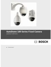
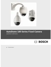
Bosch AutoDome VG4-300 Manual

Bosch Overvågningskamera AutoDome VG4-300

Læs nedenfor 📖 manual på dansk for Bosch AutoDome VG4-300 (139 sider) i kategorien Overvågningskamera. Denne guide var nyttig for 26 personer og blev bedømt med 3.5 stjerner i gennemsnit af 13.5 brugere

Side 1/139
VG4 Modular Camera System
VG4-200 | VG4-300 | VG4-500i
en User’s Manual
VG4 Modular Camera System Table of Contents | en 3
Bosch Security Systems, Inc. User’s Manual F.01U.133.268 | 6.0 | 2010.03
Table of Contents
1 Getting Started 7
1.1 Powering On 7
1.2 Establishing AutoDome Control 7
1.2.1 Basic Keyboard Operation 7
1.2.2 Keyboard Commands 8
1.3 Setting the Camera Address 8
1.3.1 FastAddress 9
1.4 Setting Passwords 9
1.4.1 Special Passwords 9
2 On-Screen Display Menu Navigation 11
2.1 Setup Menu 11
2.2 Camera Setup Menu 12
2.3 Lens Setup 14
2.4 PTZ Setup Menu 16
2.5 Display Setup Menu 17
2.6 Communication Setup Menu 19
2.7 Alarm I/O Setup 20
2.8 Rule Setup Menu 23
2.9 Language Menu 24
2.10 Advanced Feature Setup Menu (available with Series 500i only) 25
2.11 Diagnostics Menu 26
2.11.1 Alarm Status Submenu 28
3 Common AutoDome User Commands (unlocked) 30
3.1 Setting AutoPan Mode 30
3.2 Setting Preset Shots 30
3.3 Specifying a Shot or a Sector Title 30
3.4 Configuring Preposition Tours 31
3.5 Programming the Inactivity Operation 31
3.6 Recording Tours (300 and 500i Series only) 32
4 Alternative Control Protocols 33
4.1 Setting FastAddress with Alternative Protocols 33
4.1.1 Using an American Dynamics Controller 33
4.1.2 Using a Pelco Controller 35
4.2 Pelco Protocol Mode 36
4.2.1 Hardware Configuration 36
4.2.2 Pelco Keyboard Commands 37
4.2.3 Pelco Keyboard Commands 37
4.2.4 Special Preset Commands 38
4en | Table of Contents VG4 Modular Camera System
F.01U.133.268 | 6.0 | 2010.03 User’s Manual Bosch Security Systems, Inc.
5 Pelco On-Screen Menus 39
5.1 Setup Menu 39
5.1.1 Command Lock (locked) 40
5.1.2 Bosch Menu (locked) 40
5.1.3 PTZ Setup (unlocked) 41
5.1.4 Other Menus 42
6 Keyboard Commands by Number 43
7 Advanced Features 46
7.1 Alarm Rules (300 and 500i Series Only) 46
7.1.1 Controlling Alarm Rules 46
7.1.2 Alarm Rule Examples 46
7.2 AutoTrack Operation (500i Series Only) 50
7.2.1 AutoTrack Settings and Recommendations 50
7.2.2 AutoTrack Optimization 51
7.3 Virtual Masking (500i Series Only) 52
7.4 Privacy Masking (300 and 500i Series Only) 52
7.5 Motion Detection with Region of Interest (500i Series Only)
(Preset positions 90 through 99)53
7.6 Image Stabilization (500i Series Only) 53
7.7 Pre-position Tour 53
8 Using the IP AutoDome 55
8.1 Overview of Features 55
8.2 System Requirements 55
8.3 Connecting the IP AutoDome to the PC 56
8.4 Configuring the IP AutoDome Camera 57
8.5 Installing the Required Software 57
8.5.1 Changing the Network Settings 58
8.6 The LIVEPAGE 60
8.6.1 Entering a Keyboard Control Command 62
8.7 Saving Snapshots 64
8.8 Recording Video Sequences 64
8.9 Running Recording Program 64
9 VG4 Audio Connections 65
9.1 Audio Line Input Specifications 65
9.1.1 Wire Specifications 65
9.1.2 Connections 65
9.1.3 Activating Audio Reception 65
9.1.4 Enabling Audio Transmission 66
9.1.5 Configuring Gain (optional) 67
VG4 Modular Camera System Table of Contents | en 5
Bosch Security Systems, Inc. User’s Manual F.01U.133.268 | 6.0 | 2010.03
10 Configuring the IP AutoDome 68
10.1 Basic Mode: Device Access 68
10.2 Basic Mode: Date/Time 69
10.3 Basic Mode: Network 70
10.4 Basic Mode: Encoder Profile 71
10.5 Basic Mode: Audio 71
10.6 Basic Mode: Recording 71
10.7 Basic Mode: System Overview 72
10.8 Advanced Mode: Identification 72
10.9 Advanced Mode: Password 73
10.10 Advanced Mode: Date/Time 73
10.11 Advanced Mode: Display Stamping 74
10.12 Advanced Mode: Appearance 75
10.13 Advanced Mode: LIVEPAGE Functions 76
10.14 Advanced Mode: Logging 77
10.15 Advanced Mode: Picture Settings 77
10.16 Advanced Mode: Encoder Profile 78
10.17 Advanced Mode: Encoder Streams 80
10.18 Advanced Mode: Audio 80
10.19 Advanced Mode: Camera Options 81
10.20 Camera Settings Group 1 81
10.21 Camera Settings Group 2 82
10.22 Camera Settings Group 3 82
10.23 Advanced Mode: Lens 82
10.24 Lens Settings Group 1 82
10.25 Lens Settings Group 2 83
10.26 Advanced Mode: PTZ 83
10.27 PTZ Settings Group 1 83
10.28 PTZ Settings Group 2 84
10.29 Advanced Mode: Display 85
10.30 Display Settings Group 1 85
10.31 Display Settings Group 2 85
10.32 Display Settings Group 3 86
10.33 Advanced Mode: Alarm 86
10.34 Input Options 86
10.35 Output Options 87
10.36 Alarm Rules 88
10.37 Miscellaneous 93
10.38 Logs 94
10.39 Advanced Mode: Storage Management 94
10.40 Advanced Mode: Recording Profiles 95
10.41 Advanced Mode: Retention Time 97
10.42 Advanced Mode: Recording Scheduler 97
10.43 Advanced Mode: Recording Status 98
10.44 Advanced Mode: Alarm Connections 99
10.45 Advanced Mode: VCA 101
10.46 Advanced Mode: VCA Profiles 101
10.47 Advanced Mode: VCA Scheduled 105
10.48 Advanced Mode: VCA Event triggered 106
6en | Table of Contents VG4 Modular Camera System
F.01U.133.268 | 6.0 | 2010.03 User’s Manual Bosch Security Systems, Inc.
10.49 Advanced Mode: Audio Alarm 107
10.50 Advanced Mode: Alarm E-Mail 107
10.51 Advanced Mode: Alarm Task Editor 108
10.52 Advanced Mode: Network 110
10.53 Advanced Mode: Advanced 112
10.54 Advanced Mode: Multicasting 113
10.55 Advanced Mode: JPEG Posting 114
10.56 Advanced Mode: Encryption 115
10.57 Advanced Mode: Maintenance 115
10.58 Advanced Mode: Licenses 116
10.59 Advanced Mode: System Overview 116
11 Troubleshooting Guide 117
11.1 VG4 AutoDome Operation and Control 117
11.2 VG4 IP AutoDome Video and Control 120
11.3 VG4 IP AutoDome Audio 121
12 User Command Table 125
A Appendix: FastAddress Conversions 127
Index 128
VG4 Modular Camera System Getting Started | en 7
Bosch Security Systems, Inc. User’s Manual F.01U.133.268 | 6.0 | 2010.03
1 Getting Started
Install and wire the AutoDome according to the Bosch AutoDome Modular Camera System
Installation Manual. A typical system includes a keyboard, matrix switcher, monitor, and
appropriate wiring connections. Please refer to the individual produc
t manuals for complete
installation and setup instructions for each of the system components.
1.1 Powering On
When you turn the AutoDome power on there is a ten (10) second pause before the dome
starts its homing phase. During the homing phase the camera pans left and right and tilts up
and down. It also adjusts the lens focus. The entire homing phase lasts approximately 40
seconds and ends with a splash screen.
Figure 1.1 Sample VG4 Startup Splash Screen
The splash screen displays the type of AutoDome, the camera installed,
the firmware levels for
various files, and the current IP address (if the AutoDome contains the IP Communications
module). The (P) to the right of the AutoDome series indicates that the AutoDome contains
the optional modules for maintaining internal pressure.
1.2 Establishing AutoDome Control
The most common ways to interface with the AutoDome are:
Using a keyboard and on-screen display (OSD) menus. This method is the most common
and is covered in this manual.
Using the AutoDome Configuration Tool software running on a PC with Bilinx or the RS-
232/485 communication protocol. Refer to the CTFID User Manual for instructions.
Using a PC-based graphical user interface (GUI) such as the Bosch DiBos 8 software.
Refer to the DiBos 8 User Guide for instructions.
Using the Bosch IP Web interface included with the IP Communications Module.
Bosch Security Sys. AutoDome(r)
500 Series(P)
Day/Night 26X
SC Boot
FPGA
Lang. Table
VCA_boot
IP-Panel
IP Address
Subnet Mask
No Heater
FastAddress: Not Set
1.10.00.02/1.07.58.02
2.00.00.00
1.05.00.01
1.13.01.05
1.00.00.01
1.02.00.01
4.10.50.13
10. 25.118.111
255.255.248. 0
8en | Getting Started VG4 Modular Camera System
F.01U.133.268 | 6.0 | 2010.03 User’s Manual Bosch Security Systems, Inc.
1.2.1 Basic Keyboard Operation
The following tables summarize the basic operations for a standard keyboard and the
functions available to control an AutoDome camera.
Table 1.1 Typical Keyboard Functions
Table 1.2 Typical Keyboard Controls for an AutoDome Camera
1.2.2 Keyboard Commands
Keyboard control commands are composed of a sequence of three (3) inputs with the
following convention: 1) a Function
key + 2) a Command
number key(s) + 3) the Enter key.
Depending on the type of keyboard, the control function keys are labeled:
ON or AUX ON
OFF or AUX OFF
SET or SET SHOT
SHOT or SHOW SHOT
Command numbers range from 1 to 999. See Section 6 Keyboard Commands by Number,
page 43
for a complete list
of keyboard commands.
The Enter key can also be labeled with the 8 symbol.
For example, the keyboard command to make the AutoDome pan 360º continuously is:
ON-1-ENTER(press the ON key, then press the number 1 key, and then press ENTER.)
Typical Keyboard
Features
Usage
Function Keys Selects a specific control setting.
Number Keys Inputs a number from 0 to 9.
Camera Key Selects a camera number.
Enter Key Inputs a selection.
Focus Key Sets the lens focus or makes a menu selection in OSD mode.
Iris Key Sets the lens iris setting or makes a menu selection in OSD mode.
Key LEDs Indicates an active key.
LCD Displays the current status.
Joystick Controls a pan/tilt/zoom (PTZ) AutoDome camera.
Dome Operation How to control
To Pan Side to Side Move the joystick left or right.
To Tilt Up and Down Move the joystick forward and back.
To Zoom In Twist the joystick clockwise.
To Zoom Out Twist the joystick counterclockwise.
NOTICE! The convention used for control key commands in this manual is ON, OFF, SET, and
SHOT. Refer to your keyboard manual for the key naming conventions.
10 en | Getting Started VG4 Modular Camera System
F.01U.133.268 | 6.0 | 2010.03 User’s Manual Bosch Security Systems, Inc.
1.4 Setting Passwords
Passwords are used to control access to locked command menus. Unlocked commands are
available to all users. Passwords are four (4) digits in length.
1.4.1 Special Passwords
To set or change a password (locked command):
1. Press OFF-90-ENTER to turn off the command lock.
2. Press SET-802-ENTER to access the password menu.
3. Tilt the joystick up or down to choose a number. Tilt the joystick right to move to the next
number position.
4. Follow the on-screen instructions and save the password. You receive an on-screen
confirmation.
Password Security Level
0000 (default) Enables security and requires a user to enter the unlock command
OFF-90-ENTER before invoking a locked command.
9999 Disables all security and allows all users to access locked commands.
VG4 Modular Camera System On-Screen Display Menu Navigation | en 11
Bosch Security Systems, Inc. User’s Manual F.01U.133.268 | 6.0 | 2010.03
2 On-Screen Display Menu Navigation
The AutoDome is programmed through the on-screen display (OSD) menus. To access the
OSD menus, you must open the main Setup Menu.
Menu items marked with an asterisk (*) are default settings, unless otherwise noted.
2.1 Setup Menu
The main Setup Menu provides access to all programmable
AutoDome settings. It is a locked
menu that requires the user to turn off the command lock.
To open the main Setup Menu (locked command):
1. Press OFF-90-ENTER to turn off the command lock.
2. Press ON-46-ENTER to access the Main Menu.
3. Use the joystick to highlight a menu item.
4. Press Focus/Iris to open a menu.
5. Follow the on-screen instructions.
Setup Menu Choices:
NOTICE! After a period of 4.5 minutes of inactivity, a menu times-out and exits without
warning. Some unsaved settings in the current menu can be lost.
NOTICE! The AutoDome displays only those menus applicable to the AutoDome Series
configuration. Use the joystick to navigate through the menu and the Focus/Iris keys to make
a selection.
Setup Menu
Exit...
Camera Setup
Lens Setup
PTZ Setup
Display Setup
Communication Setup
Alarm Setup
Language
Advanced
Diagnostics
Focus / Iris: Select
Menu Description
Exit Exits the menu.
Camera Setup Accesses adjustable camera settings such as: white balance, gain,
sharpness, sync, line lock, backlight, shutter, and night mode.
Lens Setup Accesses adjustable lens settings such as: focus, iris, zoom speed, and
digital zoom.
PTZ Setup Accesses adjustable pan/tilt/zoom (PTZ) settings such as: Autopan, tours,
PTZ speed, inactivity period, AutoPivot, and tilt limits.
12 en | On-Screen Display Menu Navigation VG4 Modular Camera System
F.01U.133.268 | 6.0 | 2010.03 User’s Manual Bosch Security Systems, Inc.
2.2 Camera Setup Menu
The Camera Setup Menu provides access to camera settings that can be changed or
customized. Menu items marked with an asterisk (*) are the default settings.
Display Setup Accesses adjustable display settings such as: OSD, sector blanking, and
privacy masking.
Communication
Setup
Accesses communication settings such as: AutoBaud and Bilinx.
Alarm Setup Accesses the alarm settings such as: inputs, outputs, and rules (not
available with 200 Series models).
Language Displays the language.
Advanced Accesses the advanced features menu including Stabilization, AutoTrack
Sensitivity, Camera Height, and Virtual Masking (only available on 500i
Series models).
Diagnostics Displays the status of diagnostic events.
Menu Description
NOTICE! To select the Exit Menu
item from anywhere in th
e current menu, use the Zoom
command.
Camera Setup
Exit...
* White Bal: EXT ATW
* Gain Control: AUTO
* Max. Gain Level: 6 (4**)
* Sharpness 12
* Synch Mode: Internal
* Line Lock Delay: 0
* Backlight Comp: OFF
* WDR OFF
* Shutter Mode: Auto SensUP
* Shutter: 1/60
* Auto SensUP Max: 15x
* Night Mode: AUTO
* Night Mode Color: OFF
* Night Mode Threshold: 55
* Pre-Comp 1
Restore Defaults...
* = Factory Setting
** = WDR camera only
Focus / Iris: Select
VG4 Modular Camera System On-Screen Display Menu Navigation | en 13
Bosch Security Systems, Inc. User’s Manual F.01U.133.268 | 6.0 | 2010.03
Camera Setup Menu Choices:
Menu Description Sub-menu / Description Default
Setting
Exit Exits the menu.
White Balance Maintains proper color
reproduction as the
color temperature of a
scene changes. For
example, from daylight
to fluorescent lighting.
Extended ATW: Adjusts camera
color using extended range.
ATW: Adjusts camera color
constantly.
Indoor W.B.: Optimizes camera
color for typical indoor conditions.
Outdoor W.B.: Optimizes camera
color for typical outdoor
conditions.
AWB Hold: Sets the camera's
color settings for the current
scene.
Manual: Allows a user to adjust
the Red and Blue gain.
Sliding scale: – (1 to 100) +
Extended
ATW
Gain Control Electronically brightens
darker scenes which may
cause graininess in low
light scenes.
Auto or OFF AUTO
Max. Gain Level Adjusts the maximum
gain level that the gain
control adjusts to when
set to AUTO.
Sliding scale: – (1 to 6) +
(1=8db, 2=12db, 3=16db, 4=20db,
5=24db, 6=28db)
6
(4 for 36X
camera)
Sharpness Adjusts the sharpness
level of the picture.
Sliding scale: – (1 to 16) + 12
Synch Mode Sets the type of
synchronization mode
for the camera.
INTERNAL: Synchronizes camera
to an internal crystal. This choice
is recommended if there is noise
on the power line.
LINE LOCK: Synchronizes camera
to AC power. This choice
eliminates picture roll in multi-
camera systems.
INTERNAL
Line Lock Delay Optimizes the LINE
LOCK mode to eliminate
picture roll in multiphase
power applications.
Sliding scale: – (0º to 359º) +
Backlight Comp Improves image quality
when the background
illumination level is high.
ON or OFF OFF
WDR Turns the wide dynamic
range feature on or off.
ON or OFF OFF
Shutter Mode: Turns Auto SensUP on or
off.
Auto SensUP or OFF Auto
SensUP
14 en | On-Screen Display Menu Navigation VG4 Modular Camera System
F.01U.133.268 | 6.0 | 2010.03 User’s Manual Bosch Security Systems, Inc.
Shutter Adjusts the electronic
shutter speed (AES).
Sliding scale:
(60 at extreme left to 1/10000) +
1/60 sec.
(NTSC) or
1/50 sec.
(PAL)
Auto SensUP
Max.
Sets the limit for
sensitivity when the
shutter speed is set to
Auto SensUP.
15x, 7.5x, 4x, or 2x 15x
Night Mode
(Day/Night
models only)
Selects night mode (B/
W) to enhance lighting in
low light scenes.
ON, OFF, or AUTO AUTO
Night Mode
Color
(Day/Night
models only)
Determines if color
processing remains in
effect while in night
mode.
ON or OFF OFF
Night Mode
Threshold
(Day/Night
models only)
Adjusts the level of light
at which the camera
automatically switches
out of night mode (B/W)
operation.
Sliding scale: –(10 to 55)+
(in increments of 5)
10 is earlier, 55 is later
55
Pre-Comp
(not applicable
with IP
AutoDome
models)
Amplifies the video gain
to compensate for long
distance cable runs.
Sliding scale: –(1 to 10)+ 1
Restore
Defaults
Restores all default
settings for this menu
only.
Menu Description Sub-menu / Description Default
Setting
VG4 Modular Camera System On-Screen Display Menu Navigation | en 15
Bosch Security Systems, Inc. User’s Manual F.01U.133.268 | 6.0 | 2010.03
2.3 Lens Setup
The Lens Setup Menu provides access to lens settings that can be changed or customized.
Menu items marked with an asterisk (*) are the default settings.
Lens Setup Menu Choices:
Lens Setup
Exit...
* Auto Focus: SPOT
* Auto Iris: CONSTANT
* Auto Iris Level: 8
* Focus Speed: 2
* Iris Speed: 5
* Max Zoom Speed: FAST
* Digital Zoom: ON
Restore Defaults
* = Factory Setting
Focus / Iris: Select
Menu Description Sub-menu / Description Default
Setting
Exit Saves and exits the
menu.
Auto Focus Automatically
focuses on the
subject in the center
of the screen.
CONSTANT: Auto Focus is always active,
even while the camera is moving.
MANUAL: Auto Focus is inactive; manual
focus must be used.
SPOT: The camera activates Auto Focus
after the camera stops movement. Once
focused, Auto Focus is inactive until the
camera moves again.
SPOT
Auto Iris Automatically adjusts
to varying light
conditions.
MANUAL: Iris must be adjusted manually.
CONSTANT: Auto Iris is constantly active.
CONSTANT
Auto Iris
Level
Reduces the
camera's iris level for
proper exposure.
Sliding scale: – (1 to 15) + 8
Focus
Speed
Adjusts the manual
focus speed.
Sliding scale: – (1 to 8) + 2
Iris Speed Adjusts the manual
iris speed.
Sliding scale: – (1 to 10) + 5
Max. Zoom
Speed
Adjusts the manual
zoom speed.
SLOW, MEDIUM, or FAST FAST


Produkt Specifikationer

Mærke: Bosch
Kategori: Overvågningskamera
Model: AutoDome VG4-300

Har du brug for hjælp?

Hvis du har brug for hjælp til Bosch AutoDome VG4-300 stil et spørgsmål nedenfor, og andre brugere vil svare dig