BX-10 Pro
Tripod with joint head · Statief met scharnierkop
Stativ mit Gelenkkopf
Art. No. F005110
GB
Instruction Manual
NL
Handleiding
DE
Bedienungsanleitung
www.bresser.de/P15368
INFOS+DOWNLOADS:
Errors and technical changes reserved. · Fouten en technische wijzigingen voorbehouden.
Irrtümer und technische Änderungen vorbehalten.
Manual_F005110_BX-10-Pro-Tripod_en-nl-de_v082025a
Bresser GmbH
Gutenbergstraße 2
46414 Rhede · Germany
Tel. +49 (0)2872 80 74 190
service@bresser.de
www.bresser.de
@BresserEurope
Bresser Benelux / Folux B.V.
Donau 5-12
7908 HA Hoogeveen
Nederland
Tel. +31 (0)528 23 24 76
info@bresserbenelux.nl
Bresser UK Ltd.
Eden House · Enterprise Way
Edenbridge, Kent TN8 6HF
Great Britain
Phone +44 (0)1342 8370 98
sales@bresseruk.com
GB
1. ABOUT THIS MANUAL
Please keep this manual for future reference. If you sell or
transfer the device, please pass this manual on to each subse-
quent owner/user of the product.
1. GENERAL WARNINGS
• Danger of suocation! Keep packaging materials (plas-
tic bags, rubber bands, etc.) away from children! They
could play with them and choke.
• Danger of crushing! This product contains moving parts!
Tilting, clamping, or rotating these components poses a
risk of crushing limbs!
• Danger of material damage!
· During assembly, proceed carefully and only as
described in these instructions!
· Do not place any greater load on the tripod than
specied by the manufacturer!
· Keep children and animals away from the tripod!
They could knock it over and damage it.
· The manufacturer assumes no liability for damage to
the product or any devices mounted on it resulting
from incorrect assembly or failure to comply with tech-
nical specications (see “7. Technical Specications”).
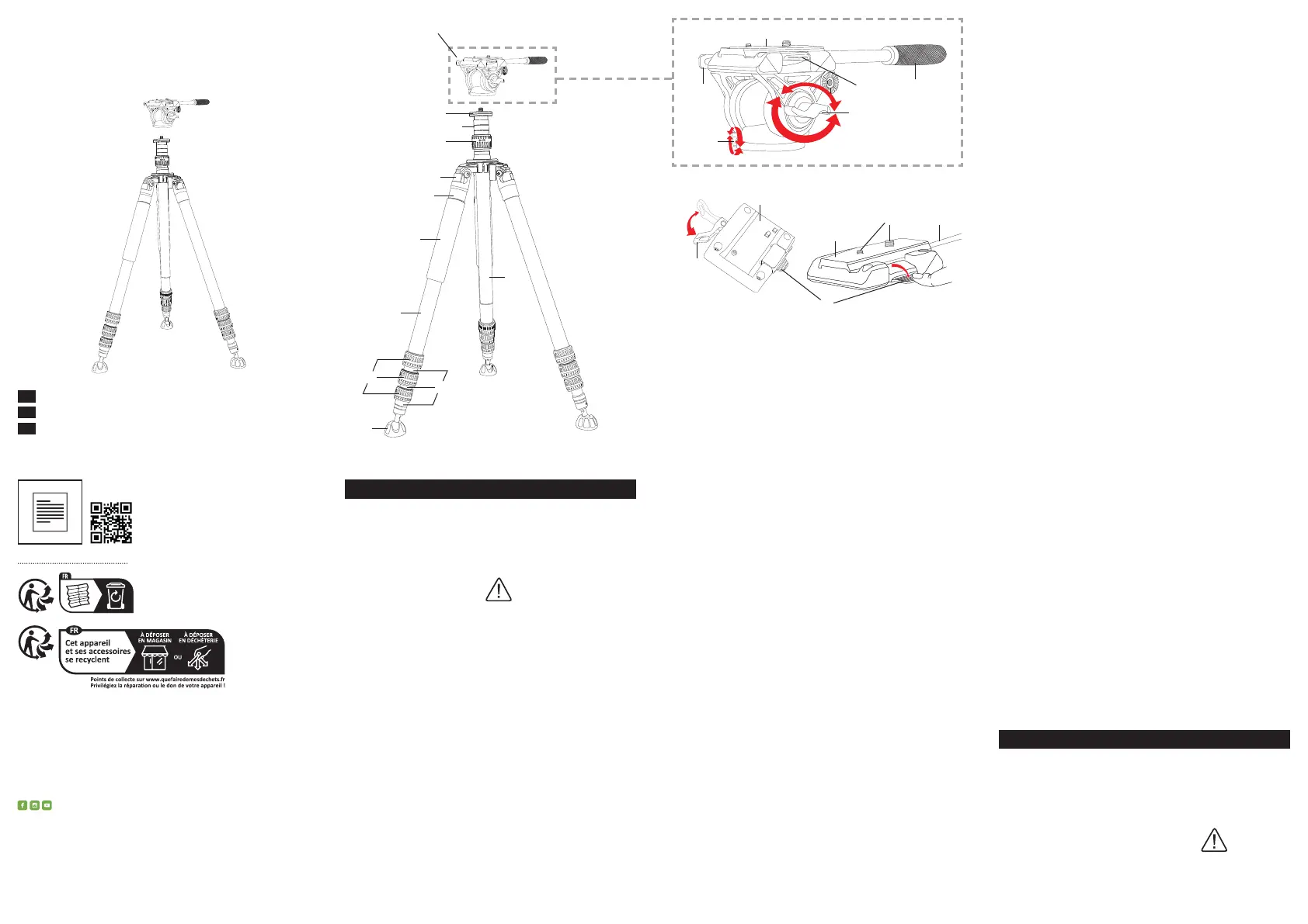
Fig. 1 turning it counterclockwise and extend the extension rod
to the desired height. Turn the clamping ring clockwise to
lock the extension rod in position.
5. USING THE JOINT HEAD
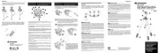
1. GENERAL INFORMATION (Fig. 2)
The joint head (1) can accommodate a variety of camera
models* and other optical devices* (e.g., spotting scopes).
The versatile rotation and tilt functions allow for virtually any
viewing position.
1.
MOUNTING A CAMERA* OR OTHER DEVICES* (Fig. 3)
1. Push the locking lever (1b) on the joint head to the side.
2. Press down the release button (1c) and pull the inter-
changeable plate out of the guide from the side.
3.
Screw the interchangeable plate with the appropriate exter-
nal thread (12) onto the internal thread of the camera or lens.
IMPORTANT!
Ensure that the removable plate is securely screwed to the
device! A device that is not securely mounted could become
detached from the removable plate during use and fall down!
4. Press down the release button and slide the interchange-
able plate with the mounted device back into the guide.
Then release the release button.
5. Push the locking lever on the joint head back to its original
position to secure the interchangeable plate.
2. AXLE MOVEMENTS
IMPORTANT!
Hold the guide handle (1f) of the joint head rmly while the
wing screws (1d, 1e) for the axial movements are loosened.
Otherwise, the joint head could ip over and damage the
mounted device.
1. Loosen the wing screw (1d) to move the joint head with
the guide handle (1f) forward or backward to the desired
position. Tighten the wing screw to x the joint head in its
current position.
2. Loosen the wing screw (1e) to move the joint head with the
guide handle (1f) sideways to the desired position. Tighten
the wing screw to x the joint head in the current position.
6. TECHNICAL DATA
Maximum tripod height: 216 cm
Maximum load capacity: 10 kg
Connecting thread: 1/4" and 3/8"
Material: metal, plastic
*not included
NL
1. OVER DEZE HANDLEIDING
Bewaar deze handleiding voor toekomstig gebruik. Als u het
apparaat verkoopt of overdraagt, geef deze handleiding dan
door aan elke volgende eigenaar/gebruiker van het product.
2. ALGEMENE WAARSCHUWINGEN
• Verstikkingsgevaar! Houd verpakkingsmaterialen
(plastic zakken, elastiekjes, enz.) buiten het bereik van
kinderen! Ze kunnen ermee spelen en zich verslikken.
Fig. 2
Fig. 3
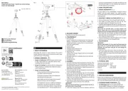
2. DELIVERY CONTENT
Tripod (A), joint head (B), carrying case (C)
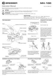
3. TEILEÜBERSICHT
1. Joint head with
a) quick release plate, b) clamping lever for release plate
xation, c) release knob, d) wing screw for forward and
backward tilt xation, e) wing screw for horizontal move-
ment and f) guide handle
2. Tripod heade
3. Tripod head joint
4. Clamping ring for extension rod
5. Clamping lever for tripod leg
6. Tripod legs with
a) grip surface, b) upper leg parts (3x) and c) extendable
leg sections (3x3)
7. Clamping rings (3x) for extendable leg section (siehe 6c)
8. Extension rod
9. Movable feet (3x)
4. ASSEMBLY
1. Grasp the tripod leg (6) by the gripping surface (6a). Press
the clamping lever (5) and simultaneously extend the tri-
pod leg outwards. Release the clamping lever to secure the
tripod leg in the desired position. Repeat this process for all
tripod legs one after the other.
2. Place the tripod with the legs extended on a surface that is
as level and stable as possible.
3. Loosen the individual clamping rings (7) for the extenda-
ble leg sections one after the other by turning them coun-
terclockwise and extend the leg sections to the desired
length. Turn the clamping rings clockwise to secure the leg
sections in the respective position.
4. Screw the joint head onto the external thread of the tripod
head using the internal thread on the underside.
IMPORTANT!
Make sure that the ball head is securely screwed onto the tri-
pod head so that it cannot fall o.
5. Loosen the clamping ring (4) for the extension rod (8) by
c
a
b
a
a
b
b
f
c
d
e
c
f