Broan BBN3306SSC Manual

Broan Emhætte BBN3306SSC

Læs gratis den danske manual til Broan BBN3306SSC (9 sider) i kategorien Emhætte. Denne vejledning er vurderet som hjælpsom af 36 personer og har en gennemsnitlig bedømmelse på 3.5 stjerner ud af 18.5 anmeldelser. Har du et spørgsmål om Broan BBN3306SSC, eller vil du spørge andre brugere om produktet?

Side 1/9
In the United States In Canada
For complete warranty statement and service parts, or to learn more about the instructions below,
please type your model number in on our website or scan the QR code. broan-nutone.com broan-nutone.ca
To obtain a paper copy of the detailed instructions, please call us. 1-800-558-1711 1-800-567-3855
EN
INSTALLATION, USE, AND CARE QUICK START MANUAL
POWERPACK INSERT MODELS BBN3306SS AND BBN3306SSC
READ AND SAVE THESE INSTRUCTIONS
Intended for domestic cooking only !
!
WARNING WARNING CAUTION
TO REDUCE THE RISK OF FIRE, ELECTRIC SHOCK, OR
INJURY TO PERSONS, OBSERVE THE FOLLOWING:
Use this unit only in the manner intended by the manufacturer. If you have
questions, contact the manufacturer at the address or telephone number
listed in the warranty.
Before servicing or cleaning unit, switch power off at service panel and lock the
service disconnecting means to prevent power from being switched on
accidentally. When the service disconnecting means cannot be locked,
securely fasten a prominent warning device, such as a tag, to the service panel.
Installation work and electrical wiring must be done by a qualified person(s)
in accordance with all applicable codes and standards, including fire-rated
construction codes and standards.
Sufficient air is needed for proper combustion and exhausting of gases
through the flue (chimney) of fuel burning equipment to prevent backdrafting.
Follow the heating equipment manufacturer’s guideline and safety standards
such as those published by the National Fire Protection Association (NFPA),
and the American Society for Heating, Refrigeration and Air Conditioning
Engineers (ASHRAE), and the local code authorities.
When cutting or drilling into wall or ceiling, do not damage electrical wiring
and other hidden utilities.
• Ducted fans must always be vented to the outdoors.
• Do not use this unit with any separate solid-state speed control device.
• To reduce the risk of fire, use only metal ductwork.
• This unit must be grounded.
When installing, servicing or cleaning the unit, it is recommended to wear
safety glasses and gloves.
When applicable local regulations comprise more restrictive installation and/or
certification requirements, the aforementioned requirements prevail on those
of this document and the installer agrees to conform to these at his own expense.
TO REDUCE THE RISK OF A RANGE TOP GREASE FIRE:
A. Never leave surface units unattended at high settings. Boilovers cause smoking
and greasy spillovers that may ignite. Heat oils slowly on low or medium settings.
B. Always turn hood ON when cooking at high heat or when flambeing food
(i.e. Crepes Suzette, Cherries Jubilee, Peppercorn Beef Flambé).
C. Clean ventilating fans frequently. Grease should not be allowed to accumulate
on fan or filter.
D. Use proper pan size. Always use cookware appropriate for the size of the
surface element.
TO REDUCE THE RISK OF INJURY TO PERSONS IN THE
EVENT OF A RANGE TOP GREASE FIRE, OBSERVE THE
FOLLOWING:*
1. SMOTHER FLAMES with a close-fitting lid, cookie sheet, or metal tray, then
turn off the burner. BE CAREFUL TO PREVENT BURNS. If the flames do not
go out immediately, EVACUATE AND CALL THE FIRE DEPARTMENT.
2. NEVER PICK UP A FLAMING PAN - You may be burned.
3. DO NOT USE WATER, including wet dishcloths or towels - violent steam
explosion will result.
4. Use an extinguisher ONLY if:
A. You know you have a Class ABC extinguisher and you already know how to
operate it.
B. The fire is small and contained in the area where it started.
C. The fire department is being called.
D. You can fight the fire with your back to an exit.
* Based on “Kitchen Fire Safety Tips” published by NFPA.
For indoor residential use only.
To reduce risk of fire and to properly exhaust air, be sure to duct air
outside. Do not vent exhaust air into spaces within walls or ceilings
or into attics, crawl spaces, or garages.
Take care when using cleaning agents or detergents.
Avoid using food products that produce flames under the Range
Hood.
For general ventilating use only. Do not use to exhaust hazardous
or explosive materials and vapors.
To avoid motor bearing damage and noisy and/or unbalanced
impellers, keep drywall spray, construction dust, etc. off power
unit.
Your hood motor has a thermal overload which will automatically
shut off the motor if it becomes overheated. The motor will restart
when it cools down. If the motor continues to shut off and restart,
have the hood serviced.
The bottom of the hood MUST NOT BE LESS than 24 and
recommended at a maximum of 30above the cooktop for best
capture of cooking impurities.
Use only with range hood cord connection kits that have been
investigated and found acceptable for use with this model range
hood.
Please read specification label on product for further information
and requirements
.
!!
!
1. INSTALL THE DUCTWORK (DUCTED
INSTALLATION ONLY)
NOTE: To reduce the risk of fire, use only metal ductwork.
1.
Decide where
the ductwork
will run between
the powerpack
insert and the
outside. (FIG. 1)
2. A straight, short
du ct run will
allow the hood
to perform most
efficiently.
3. Long duct runs,
e lb o ws , an d
transitions will
reduce the performance of the hood. Use as few of them as possible.
Larger ducting may be required for best performance with longer duct runs.
4. Install wall cap or roof cap (sold separately). Connect metal ductwork to
cap and work back towards the hood location. Use 2” metal foil duct tape
to seal the joints between ductwork sections.
24" - 30" MIN MAX
ABOVE COOKING SURFACE
POWERPACK
INSERT W ALL CAP
R OOF CAP
8" 6" OR ROUND DUCT
OR
3¼" 10" X DUCT
H OUSE WIRING
3¼" 10" X DUCT
FIG. 1
Detach and set aside the 3¼” x 10” adapter/damper and the 6-in.-round
damper (grey parts in FIG. 2) from back and side of the powerpack insert by
removing their 2 retaining screws. Discard the screws.
Detach the cabinet brackets (grey part in FIG. 3) from the back of the
powerpack insert by removing its 3 retaining screws. Discard the screws.
Fold up and down the bracket until it is split in two separate parts (FIG. 4).
Keep the brackets for possible further use.
NOTE: Both cabinet brackets have one wide edge and one narrow edge
(FIG. 5), to cover all installation configurations depending on cabinet widths.
2. REMOVE THE ADAPTER/DAMPER AND
6-IN. ROUND DAMPER
3. REMOVE THE CABINET BRACKETS
FIG. 4
FIG. 2
SCREWS
FIG. 3
Wide edge
Narrow edge
FIG. 5
4. PREPARE THE CABINET
NOTES: A. The unit has to be installed inside the cabinet.
B. The unit should be mounted centered laterally over the cooktop burners.
C. For back to front position, the unit must be mounted according to local building codes.
1. Cut a hole in the bottom of the cabinet, using the dimensions shown (FIG. 6).
2. Measure the remaining material of the cabinet bottom sides (C in FIG. 7), if it is 1/4” or more, there is no need to use the cabinet brackets. Go to step 7.
3. When there is less than 1/4” remaining material ( ), carefully remove those strips. Measure the cabinet inner width ( in FIG. 7). Refer to the table below C D
to see which cabinet bracket edge configuration must be used.
WARNING
The cabinet must be secured to wall studs or other wooden framework behind the drywall to support the weight of this
unit. Failure to do so may cause personal injury or damage to countertop or cooktop.
!
N ARROW EDGE WIDE EDGE
D
From 28-1/16” to < 28-1/2”
D
From 28-1/2” to 29”
FIG. 7
A = 10¼”
B = 28 ¹/16
CUT A HOLE IN THE BOTTOM
OF THE CABINET
FIG. 6
4. Pay attention to the Ease of Install hooks location on the unit (distance given from unit front flange, FIG. 8). Measure and mark the position of the Ease
of Install hooks (shown as in FIG.9) on both cabinet side walls. Remove the unit.E
FIG. 8
FRONT
UNIT TOP VIEW
5. Install the cabinet brackets as follow (FIG. 9):
Align the bracket flush with the bottom of
the right cabinet side panel, with the
hooks marked position ( ) between the E
bottom embossed holes. For the narrow
edge configuration, trace a line on
the top of the bracket. For wide edge
configuration, trace a line at the bottom
of the central slots.
Lift the bracket flush with the marked
lined. Assemble the bracket to the
cabinet side panel using 2 no. 8 x 5/8”
wood screws (included in parts bag)
through the upper holes.
NOTE: Do not use the embossed holes to
attach the bracket to the cabinet.
Repeat steps   to for the left
cabinet side panel.
FIG. 9
Wide edge
configuration
FLUSH
E
Narrow edge
configuration
E
FLUSH
1105018C
For ADA compliance installation guidelines, please type the model number into our website.
RECOMMENDED TOOLS AND ACCESSORIES
Measuring tape
Phillips screwdriver no. 2
Nut driver or socket 3/8
Flat blade screwdriver
(to open knock-out holes)
Saw (to cut holes in cabinet)
Sheet metal shears
Pliers
Metal foil duct tape
Scissors (to cut metal foil duct tape)
Pencil
Wire stripper
2 Appropriate wire nuts
Strain relief, 7/8” diameter (to secure
house wiring cable to the hood)
4. PREPARE THE CABINET ( )CONT D
This powerpack insert is factory shipped to exhaust vertically; however, it is
possible to make it exhaust horizontally (3¼” x 10” ducting only).
8. Cut the hole for the
ho rizontal e xhaust
through the back wall
of the cabinet using
the dimensions shown.
(FIG. 13).
HORIZONTAL EXHAUST INSTALLATION ONLY
""
"
3/4"
FIG. 13
CABINET BOTTOM
CABINET
BACK WALL
8. From inside the unit,
detach the back plate
(grey part in FIG. 20)
by removing its both
retaining nuts using 3/8”
diameter socket. Set
aside the nuts and plate.
6. INSTALL THE UNIT ( )CONT D
FIG. 21
HOLES
9. Install the back plate on
top of the unit, where
the blower support plate
was. Orient the holes
n e arb y th e co rn ers
towards the back of the
unit. Assemble to the top
of the unit using 6 screws
previously removed in
step 7 (FIG. 21).
5. PREPARE THE UNIT
A LL INSTALLATIONS
1. If present, remove all protective polyfilm from the unit and/or parts.
2. Remove the grease
filters by pushing down
on latch tab and tilting
the filters downward
(FIG. 14). Set aside the
filters.
3. D i s a s s e m b l e t h e
electrical compartment
cover (grey part in
FIG. 15) from inside
the unit by removing
its retaining screw.
Remove the parts bag
behind the cover. Set
aside the parts bag and
the cover along with its
screw.
FIG. 14
SCREW
FIG. 15
4. Punch out one of the
two knock-out holes.
Install an appropriate
7/8 diameter strain
relief (not included,
grey part in FIG. 16).
NOTE: The HCK44
cord connection kit
(optional) can be used
instead of the house
power cable. Refer to
the instruction packed
with the HCK44 cord connection kit.
FIG. 16
HORIZONTAL EXHAUST INSTALLATION ONLY
5. Remove and set aside
the screw (circled in
FIG. 17) on the top,
inside of the unit.
NOTE: This screw
might be present or
not.
FIG. 17
FIG. 20
NUTS
V ERTICAL EXHAUST INSTALLATION ONLY
10. F o r r e c t a n g u l a r
ducting, use 2 included
no. 8-18 x 1/4” metal
screws to attach the
included 3¼ x 10
adapter damper on top
of the unit, over the
blower exhaust opening
(FIG. 22).
NOTE: The damper hinge
must be towards the
front of the unit.
For round ducting,
u s e 4 i n c l u d e d
n o . 8 - 1 8 x 1 / 4
metal screws to attach
the included 6-in. round
(or 8-in. round) adapter
damper on top of the
unit, over the blower exhaust opening (FIG. 22, 6-in. round shown).
NOTE: The damper hinge must be parallel to the sides of the unit.
FIG. 22
HINGE
HINGE
6. INSTALL THE UNIT
1. Run house power cable
between service panel
and unit location. Stub out
a 2-foot length of power
cable inside the cabinet.
Insert the power cable
in the unit through the
7/8” diameter strain relief
previously installed.
NOTE: Not necessary if
the optional HCK44 cord
connection kit is used.
2. Insert the unit in the
cabinet, until you feel a
click from both sides
of the unit, confirming
that the Ease of Install
hooks rest on the top of
the cabinet bottom sides
, or cabinet brackets
  or (FIG. 23). Move
the unit from left to right,
from rear to front and up
to ensure the Ease of
Install hooks are retaining
the unit inside the cabinet.
NOTE: The unit will be
protruding below the
cabinetry until tightened.
FIG. 23
4. From inside the unit, slide the
x 10 adapter/damper in
the horizontal duct, then attach
it to the unit using aluminum
duct tape all around the joint
(FIG. 26). Ensure the damper
opens as shown in damper
side view.
HORIZONTAL EXHAUST INSTALLATION ONLY
FIG. 26
DAMPER
SIDE
VIEW
DUCT
5. Insert the blower with its support
plate inside the unit, where
the back plate was initially
(A). Attach to the unit using
2 nuts previously removed in
step 8 in PREPARE THE UNIT
section ( ) (FIG. 27).B
FIG. 27
A
B
6. Re i nstal l and se cu re the
faceplate to the unit using its
4 retaining screws (two per side,
circled in FIG. 28). Plug the
blower cable to its connector on
faceplate (FIG. 28).
FIG. 28
FIG. 29
7. CONNECT DUCTWORK
V ERTICAL EXHAUST INSTALLATION ONLY
Ducted Installation
Use 6-in. round, 8-in. round
or 3¼ x 10” metal duct to
connect the adapter damper
on the top of the unit to the
ductwork above (FIG. 30, 8-in.
round not shown). Seal the
joint using aluminum duct tape.
Non-Ducted Installation
The HARKBN30 non-duct kit is required for this type of installation
(purchase separately). To install, follow the instructions packed with
the kit.
3. Lift the unit until contact is made
between the unit flange and
cabinet. Secure the unit to the
cabinet using 4 no. 8 x 5/8wood
screws included in parts bag
(2 screws per side). Use upper
or lower holes (1, 2, 3, 4, 5 or
6) (FIG. 25).
WARNING
The Ease of Install hooks TEMPORARILY hold the unit in
place. The unit MUST BE secured to the cabinet using the
included 4 screws.
!
WARNING
Never use this unit as a shelf.
!
FIG. 25
5. PREPARE THE UNIT ( )CONT D
7. Remove the 6 screws (2
per side and 2 in front)
retai n in g the bl o wer
support plate to the top
of the unit (FIG. 19).
Carefully lift out and set
aside the blower with its
support plate. The blower
will be reinstalled later in
the unit.
6. Measure the distance
between both bottom
bracket edges ( ) F
(FIG. 10). The table
below shows the
approriate distance
needed.
If the measured distance
needs to be shortened,
screw two no. 8-32 x 1/4”
machine screws, in each
bottom embossed cabinet
brackets hole; this will
slightly bend the bottom
part of the brackets
(FIG. 11). Screw both
brackets until the
appropriate distance is obtained.
F
FIG. 10
F
Screws in bottom
embossed holes
FIG. 11
7. There are 3 different
sizes of filler included
wi t h th e se u n it s,
designed to fit up to
13-in. depth cabinets.
For up to 15-in. depth
cabinets, another set
of 4 fillers is available
(order HADTBN30).
C h o o s e t he f i ll e r
that fits to cover the
back bottom edge of
the cabinet. Use 4
no. 6 x 1/2” truss head
wood screws (included)
to mount it (FIG. 12). FIG. 12
CAUTION
Never use an electric screwdriver or drill to screw the
filler to the bottom edge of cabinet; use a standard
screwdriver.
NOTE: If, for any reason, the unit
has to be removed from
the cabinet, it is possible
to disengage the Ease of
Install hooks. To do so,
while holding and pushing
on one side of the unit,
lift simultaneously Ease of
Install hooks levers (1 and , grey parts in FIG. 24) in the other side 2
of the unit until the hooks are retracted.
FIG. 24
12
HORIZONTAL EXHAUST INSTALLATION ONLY CONT D ( )
6. Unplug the blower cable
from its connector on
faceplate. Disassemble
the faceplate from the
unit by removing its
4 retaining screws
(two per side, circled in
FIG. 18). Set aside the
faceplate along with its
screws.
FIG. 18
N ARROW EDGE WIDE EDGE
F
From 27-7/8” to < 28-1/16”
F
From 28-1/16” to 28-5/16”
FIG. 19
SCREWS
SCREWS
SCREWS


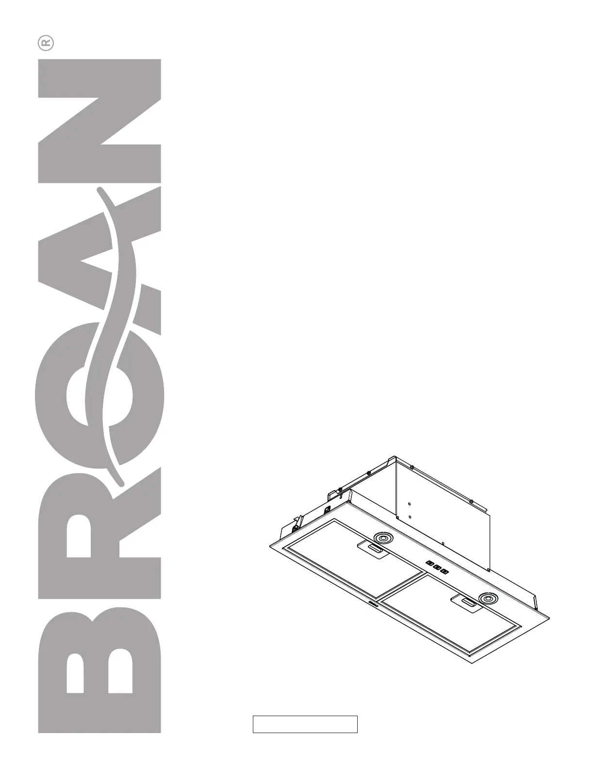
Produkt Specifikationer

Mærke: Broan
Kategori: Emhætte
Model: BBN3306SSC

Har du brug for hjælp?

Hvis du har brug for hjælp til Broan BBN3306SSC stil et spørgsmål nedenfor, og andre brugere vil svare dig


Emhætte Broan Manualer

Broan

Broan BCSEK136WW Manual

12 Januar 2025
Broan

Broan BKDB136WW Manual

11 Januar 2025
Broan

Broan Elite RMIP45 Manual

1 September 2024
Broan

Broan Elite 619004 Manual

1 September 2024
Broan

Broan BWS1304SS Manual

1 September 2024
Broan

Broan EWS1306BLS Manual

1 September 2024
Broan

Broan BWP1304SS Manual

1 September 2024
Broan

Broan PM250 Manual

1 September 2024

Emhætte Manualer

Nyeste Emhætte Manualer