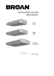
Broan Silhouette 153604 Manual

Broan Emhætte Silhouette 153604

Læs gratis den danske manual til Broan Silhouette 153604 (8 sider) i kategorien Emhætte. Denne vejledning er vurderet som hjælpsom af 9 personer og har en gennemsnitlig bedømmelse på 4.9 stjerner ud af 5 anmeldelser. Har du et spørgsmål om Broan Silhouette 153604, eller vil du spørge andre brugere om produktet?

Side 1/8
LEA Y CONSERVE
ESTAS INSTRUCCIONES
INSTALLER: Leave This Manual With
Homeowner. HOMEOWNER: Use
and Care Information on page 4.
INSTALADOR: Deje este manual con el dueño
de la casa. DUO DE LA CASA:
Informacn acerca del uso y mantenimiento
en la página 4.
READ AND SAVE
THESE INSTRUCTIONS
PRECAUCION
PARA REDUCIR EL RIESGO DE INCENDIO, CHOQUE
ELECTRICO, O LESION A PERSONAS, PROCURE LO
SIGUIENTE:
1. Utilice esta unidad sólo en la manera prescrita por el
fabricante. Si tiene usted alguna pregunta, comuníquese
con el fabricante a la dirección o el teléfono indicados en
la garantía.
2. Antes de limpiar o de poner en servicio la unidad, apague
el interruptor en el panel de servicio, y asegure el panel
de servicio para evitar que se encienda accidentalmente.
Cuando el dispositivo para desconectar el servicio
eléctrico no puede ser cerrado con algún tipo de traba,
sujete fuertemente al panel de servicio, una etiqueta de
advertencia prominente.
3. Todo trabajo de instalación y cableado eléctrico debe
ser realizado por personal calificado y de acuerdo con
todos los códigos y normas pertinentes, incluyendo los
códigos y normas relacionados con construcción
clasificada para incendio.
4. Aire suficiente es necesario para facilitar la combustión
adecuada y la salida apropiada de gases por la chimenea
de la unidad y para evitar corrientes de aire invertidas.
Siga las instrucciones y medidas de seguridad del
fabricante del equipo y de las sociedades profesionales
de equipos de calentadores y los reglamentos de
seguridad locales.
5. A cortar o perforar la pared o el techo, no dañe el cableado
eléctrico u otros servicios públicos ocultos a la vista.
6. No utilice este ventilador con ningún dispositivo de
una control de velocidad de estado lido adicional.
7. Los abanicos con ducto deberán siempre tener una
salida hacia el exterior.
8. Para reducir el riesgo de incendio, use sólo ductos de
metal.
9. Uso con el kit aprobado del la conexión de la cuerda
solamente.
10.Esta unidad se debe instalar con tierra efectiva.
PARA REDUCIR EL RIESGO DE INCENDIO DEBIDO A
GRASA ACUMULADA EN LAS HORNILLAS:
1. Nunca deje sin atender las unidades de superficie
cuando tengan ajustes altos. Los reboses pueden
provocar humo y derrames grasosos que se pueden
incendiar. Caliente lentamente el aceite en un ajuste
bajo o medio.
2. Siempre ENCIENDA la campana cuando cocine con
alta temperatura o cuando cocine alimentos que se
puedan incendiar.
3. Limpie con frecuencia los ventiladores. No debe permitir
que la grasa se acumule en el ventilador ni en el filtro.
4. Utilice un sartén de tamaño adecuado. Siempre utilice
el utensilio adecuado al tamo del elemento de
superficie.
PARA REDUCIR EL RIESGO DE LESION A PERSONAS
RESULTADO DE UN INCENDIO DEBIDO A GRASA ACUMULADA
EN LAS HORNILLAS, PROCURE LO SIGUIENTE:*
1. AHOGUE LAS LLAMAS con una tapa ajustada o charola
de metal, después apague la hornilla. TENGA CUIDADO
A FIN DE EVITAR QUEMADURAS. Si las llamas no se
apagan de inmediato, EVACUE Y AVISE A LOS
BOMBEROS.
2. NO LEVANTE NUNCA UNA SARTEN QUE ESTE EN
LLAMAS - Usted se podrá quemar.
3. NO UTILICE AGUA, incluyendo toallas de cocina mojadas
- puede resultar una explosión de vapor violenta.
4. Utilice un extinguidor SOLAMENTE si:
A. Usted sabe que tiene un extinguidor de clase
ABC y lo sabe utilizar.
B. El incendio es pequo y contenido dentro del
área donde se inició.
C. Los bomberos han sido avisados.
D. Usted puede combatir el incendio con una salida a
su espalda.
* Basado en las recomendaciones para “Seguridad en la
Cocina” publicadas por la NFPA de los EEUU.
MODEL 1530
SILHOUETTE
RANGE HOOD
MODELO 1530
SILUETA
EXTRACTOR
WARNING
TO REDUCE THE RISK OF FIRE, ELECTRIC SHOCK,
OR INJURY TO PERSONS, OBSERVE THE FOLLOW-
ING:
1. Use this unit only in the manner intended by the
manufacturer. If you have questions, contact the
manufacturer at the address or telephone num-
ber listed in the warranty.
2. Before servicing or cleaning unit, switch power
off at service panel and lock the service discon-
necting means to prevent power from being
switched on accidentally. When the service dis-
connecting means cannot be locked, securely
fasten a prominent warning device, such as a tag,
to the service panel.
3. Installation work and electrical wiring must be
done by a qualified person(s) in accordance with
all applicable codes and standards, including fire-
rated construction codes and standards.
4. Sufficient air is needed for proper combustion and
exhausting of gases through the flue (chimney) of
fuel burning equipment to prevent backdrafting.
Follow the heating equipment manufacturer’s
guideline and safety standards such as those pub-
lished by the National Fire Protection Association
(NFPA), and the American Society for Heating, Re-
frigeration and Air Conditioning Engineers
(ASHRAE), and the local code authorities.
5. When cutting or drilling into wall or ceiling, do not
damage electrical wiring and other hidden utilities.
6. Do not use this range hood with an additional
speed control device.
7. Ducted fans must always be vented to the out-
doors.
8. To reduce the risk of fire, use only metal ductwork.
9. Use with approved cord-connection kit only.
10. This unit must be grounded.
TO REDUCE THE RISK OF A RANGE TOP GREASE
FIRE:
1. Never leave surface units unattended at high set-
tings. Boilovers cause smoking and greasy
spillovers that may ignite. Heat oils slowly on low
or medium settings.
2. Always turn hood ON when cooking at high heat
or when cooking flaming foods.
3. Clean ventilating fans frequently. Grease should
not be allowed to accumulate on fan or filter.
4. Use proper pan size. Always use cookware ap-
propriate for the size of the surface element.
TO REDUCE THE RISK OF INJURY TO PERSONS
IN THE EVENT OF A RANGE TOP GREASE FIRE,
OBSERVE THE FOLLOWING:*
1. SMOTHER FLAMES with a close-fitting lid, cookie
sheet, or metal tray, then turn off the burner. BE
CAREFUL TO PREVENT BURNS. If the flames
do not go out immediately, EVACUATE AND CALL
THE FIRE DEPARTMENT.
2. NEVER PICK UP A FLAMING PAN - You may be
burned.
3. DO NOT USE WATER, including wet dishcloths
or towels - a violent steam explosion will result.
4. Use an extinguisher ONLY if:
A. You know you have a Class ABC extinguisher
and you already know how to operate it.
B. The fire is small and contained in the area where
it started.
C. The fire department is being called.
D. You can fight the fire with your back to an exit.
* Based on “Kitchen Fire Safety Tips” published by
NFPA.
MODEL 1530
SILHOUETTE RANGE HOOD
MODELO 1530
SILUETA EXTRACTOR
!
INTENDED FOR
DOMESTIC COOKING ONLY.
!
!
PREVISTO PARA COCINAR
DOMÉSTICO SOLAMENTE.
!
PRECAUCION
1. Solamente para uso general de ventilación. No utilice
para descargar materiales o vapores riesgosos o
explosivos.
2. Para evitar daños al motor y evitar que las navajas del
abanico emitan mucho ruido o estén fuera de balance,
mantenga el motor libre de pelusa, polvo, etc.
3. Si usa un termóstato con este producto, el abanico puede
arrancar automáticamente. Para reducir el riesgo de
lesiones, apague la fuerza eléctrica en el panel de
servicio y cierre con llave el panel de servicio para evitar
que alguien prenda la fuerza eléctrica accidentalmente.
4. El motor de su extractor tiene dispositivo de sobrecarga
térmica, al cual automáticamente apagará el motor si se
sobrecalienta. El motor funcionará de nuevo cuando se
enfríe. Si el motor continua apagándose y arrancando,
hágalo componer.
5. Por favor lea la etiqueta con las especificaciones del
equipo para otros requisitos y mayor información.
2
FIG. 3
FIG. 4
FIG. 1
FLUSH BOTTOM CABINET
GABINETE CON FONDO A RAS
FIG. 2
CABINET BOTTOM VIEW
VISTA DESDE LA PARTE
INFERIOR DEL GABINETE
CABINET FRONT
FRENTE DEL
GABINETE
CABINET CENTER LINE
LINEA CENTRAL DEL GABINETE
0,95 CM DIA.
CLEARANCE
HOLES
AGUJEROS DEL
CLARO
ELECTRICAL KNOCKOUTS
PLACAS DE QUITAR GOLPEANDO
FIG. 5
ACCESS COVER
TAPA DE ACCESO
RECESSED BOTTOM CABINET
GABINETE CON FONDO AHUECADO
PLANIFIQUE LA
INSTALACION
Su nuevo extractor cabrá en la parte inferior de un gabinete
estándar de 76,2 cm con la parte inferior a ras o ahuecada,
con o sin marco, que tenga una profundidad mínima de
27,94 cm desde la parte frontal hacia a la pared.
El ducto de la unidad sube verticalmente. A un ducto hori-
zontal se lo puede instalar como se muestra.
Para operacn segura, el extractor p2-ya montado tiene que estar
a un mínimo de 45,72 cm sobre la superficie de la cocina.
Para una instalación más fácil, al extractor debe de
instarselo en el gabinete antes de montar el gabinete en
la pared.
NOTESE
QUITE EL CAJÓN DE VIDRIO DE LA UNIDAD ANTES
DE INSTALAR EL EXTRACTOR EN EL GABINETE
PARA EVITAR DAÑAR EL CAJÓN. VÉASE PASO 13
EN PÁGINA 3.
A este extractor se lo puede instalar fácilmente siguiendo
estos pasossicos:
Marque y corte el hueco en la parte inferior del gabinete.
Sujete el extractor al gabinete.
Monte el gabinete sobre la pared.
Conecte los ductos y el cableado. (FIG. 1)
INSTALE EL EXTRACTOR
1.
Marque y corte el hueco en la parte inferior del gabinete.
(FIG. 2)
Prepare la parte inferior del gabinete como se muestra
en Fig. 2. Asegúrese que localice el hueco y los cuatro
agujeros desde la parte frontal del gabinete para
asegurarse que se monte a ras.
2. Sujete el conector para el regulador/ducto. (FIG. 3)
Use dos (2) tornillos (suministrados) para sujetar el
conector al bastidor. La placa del regulador debe de
abrirse en la dirección de la flecha.
3. Quite la placa de quitar golpeando.
Escoja, p2-ya sea la parte superior, o parte lateral del
bastidor para la entrada de cable eléctrico. Quite la placa
de quitar golpeando apropiada.
4. Ponga el bastidor dentro del hueco. (FIG. 4)
Con cuidado meta el bastidor dentro del hueco del
gabinete con el control de deslizar hacia en frente.
5. Quite la tapa de acceso. (FIG. 5)
""
24-1/2"
62,23 CM
13-1/2"
34,29 CM
2-5/8"
6,67 CM
7"
17,78 CM
14"
35,56 CM 25-5/8"
65,09 CM
9-1/2"
24,13 CM
1-5/8"
4,13 CM
(4) 3/8" DIA.
18" MIN.
45,72 CM MIN.
11 "
27,94 CM
MIN.
(INSIDE)
(ADENTRO)
18" MIN.
45,72 CM MIN.
11"
27,94 CM
MIN.
(INSIDE)
(ADENTRO)
CUT-OUT
HUECO
#8-18 x 3/8"
SLIDE CONTROL
CONTROL DE DESLIZAR
CAUTION
1. For general ventilating use only. Do not use to exhaust
hazardous or explosive materials and vapors.
2. To avoid motor bearing damage and noisy and/
or unbalanced impellers, keep drywall spray,
construction dust, etc. off power unit.
3. When using a thermostat with this product, fan may
start automatically. To reduce the risk of injury, switch
power off at service panel and lock service panel to
prevent power from being switched on accidentally.
4. Your hood motor has a thermal overload which will
automatically shut off the motor if it becomes
overheated. The motor will restart when it cools
down. If the motor continues to shut off and restart,
have the hood serviced.
5. Please read specification label on product for further
information and requirements.
PLAN THE INSTALLATION
Your new hood will fit a standard 30" wide flush bot-
tom or recessed bottom, framed or frameless kitchen
cabinet which has a minimum depth of 11" from face
to inside of back wall.
The unit is ducted vertically. Horizontal ducting can
be accomplished as shown.
For safe operation, the mounted hood must be a mini-
mum of 18" above the cooking surface.
For easiest installation, range hood should be installed
in cabinet before mounting cabinet to wall.
NOTE
REMOVE GLASS DRAWER FROM UNIT BEFORE
INSTALLING HOOD IN CABINET TO PROTECT
DRAWER FROM DAMAGE. SEE STEP 13 ON
PAGE 3.
This hood can easily be installed by following these
basic steps:
Mark and cut out cabinet bottom.
Secure hood to cabinet.
Mount cabinet on wall.
Connect ductwork and power cable. (FIG. 1)
INSTALL THE HOOD
1. Mark and cut-out cabinet bottom. (FIG. 2)
Prepare the cabinet bottom as shown in Figure 2.
Be sure to locate the cut-out and four holes from
the front of the cabinet to assure a flush mount.
2. Attach damper/duct connector. (FIG. 3)
Use two (2) screws (provided) to attach connec-
tor to housing. Damper flap should open in direc-
tion indicated by arrow.
3. Remove electrical knockout.
Choose either the top or side of housing for elec-
trical cable entrance. Remove the appropriate
knockout.
4. Set housing into opening. (FIG. 4)
Carefully lower housing into cabinet opening with
slide control to the front.
5. Remove access cover. (FIG. 5)


Produkt Specifikationer

Mærke: Broan
Kategori: Emhætte
Model: Silhouette 153604

Har du brug for hjælp?

Hvis du har brug for hjælp til Broan Silhouette 153604 stil et spørgsmål nedenfor, og andre brugere vil svare dig


Emhætte Broan Manualer

Broan

Broan BCSEK136WW Manual

12 Januar 2025
Broan

Broan BKDB136WW Manual

11 Januar 2025
Broan

Broan Elite RMIP45 Manual

1 September 2024
Broan

Broan Elite 619004 Manual

1 September 2024
Broan

Broan BWS1304SS Manual

1 September 2024
Broan

Broan EWS1306BLS Manual

1 September 2024
Broan

Broan BWP1304SS Manual

1 September 2024
Broan

Broan PM250 Manual

1 September 2024

Emhætte Manualer

Nyeste Emhætte Manualer