1
Replacement Wire Harness Instructions
Model 041D9204
To prevent possible SERIOUS INJURY or
DEATH:
• Disconnect ALL electric and battery
power BEFORE performing ANY
service or maintenance.
Before you begin
1. Disconnect both electrical and battery
power (if applicable) to the garage door
opener.
2. Remove the LED light pods.
a. Pull the top sides of the light lens and
rotate the light lens down.
b. Unplug the LED light pod by
squeezing the connector.
c. Squeeze the light lens clips to remove
the lens from the end panel.
3. Remove the 8 screws to the chassis
cover and remove it.
4. Disconnect the wires on the wire
terminal.
5. Remove screws from end panel.
6. Unplug the wire harness from the logic
board and end panel.
7. Unplug the ORANGE AND WHITE wires
from the LED Driver board.
• To prevent damage to the receiver
logic board, DO NOT touch printed
circuit board of replacement receiver
logic board during installation.
• ALWAYS wear protective gloves and
eye protection when changing the
battery or working around the battery
compartment.
WARNING: This product can
expose you to chemicals including
lead, which are known to the State
of California to cause cancer or
birth defects or other reproductive
harm. For more information go to
www.P65Warnings.ca.gov.
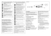
Logic Board LED Light
Driver Board
To Travel Module
Terminal Block
Ground
White
Orange
Black
White
White
Green
8. Follow the WHITE AND BLACK wires
from the LED driver board and cut the
wire ties.
9. Remove the LED driver board and end
panel.
10. Clip any wire ties from the existing wire
harness.
11. Unplug the WHITE AND BLACK wires
from the terminal block, and remove the
GREEN ground wire.
12. Install the new wire harness.
13. White to white on terminal block, black
to black on terminal block.
14. Attach GREEN ground wire to chassis.
15. Replace travel module wire harness if
necessary.
16. Reinstall LED Driver board end panel.
17. Attach WHITE AND ORANGE wires to
LED driver board.
18. Reconnect wires to logic board.
19. Reconnect WHITE AND BLACK wires
from LED Driver board to logic board
end panel connector plate.
20. Use wire ties to hold all wires together.
21. Reinstall chassis cover to unit.
22. Connect wires to the wire terminal.
a. Door Control Wires:
i. White wire into the white terminal
ii. White/red wire into the red terminal
b. Safety Sensor Wires:
i. White wires into the white terminal
ii. White/black wires into the grey
terminal
23. Make sure the antenna wire is hanging
down.
24. Reattach the LED light pods.