Chauvin Arnoux C.A 703 Manual


Læs gratis den danske manual til Chauvin Arnoux C.A 703 (4 sider) i kategorien Multimeter. Denne vejledning er vurderet som hjælpsom af 45 personer og har en gennemsnitlig bedømmelse på 4.3 stjerner ud af 23 anmeldelser. Har du et spørgsmål om Chauvin Arnoux C.A 703, eller vil du spørge andre brugere om produktet?

Side 1/4
DESCRIPTION
BESCHREIBUNG
DESCRIZIONE
DESCRIPCIÓN
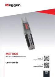
FACE AVANT – FRONT PANEL
VORDERSEITE
FACCIA ANTERIORE - FRONTAL
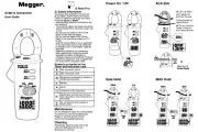
1. Capteur détection de tension sans contact FR
-Contact free voltage detection sensor GB
Spannungsprüfer berührungslo D
Sensore rilevazione di tensione senza contatto I
Sensor detección de tensión sin contacto E
2. Barre lumineuse d’indication de tension FR
Voltage indication light bar GB
Spannungsanzeige D
Barra luminosa indicante la tensione I
Barra luminosa de indicación de tensión E
3. LCD FR
LCD GB
D LCD
I LCD
E LCD
4. Touche de sélection de mesure FR
Measurement selection key GB
Messwahltaste D
Tasto di selezione di misura I
Tecla de selección de medida E
5. Commutateur FR
Switch GB
D Umschalter
Commutatore I
Conmutador E
6. Torche lumineuse FR
Flashlight GB
D Stablampe
I Torcia luminosa
E Torcha luminosa
7. Touche pour actionner la torche lumineuse FR
Flashlight On key GB
Taste für die Stablampe D
Tasto per azionare la torcia luminosa I
Tecla para accionar la torcha luminosa E
8. Touche HOLD FR
HOLD key GB
D Taste HOLD
I Tasto HOLD
E Tecla HOLD
9. Trappe à piles FR
Battery compartment GB
Batteriefach D
Sportello delle pile I
Tapa de pilas E
10. Pointes de touches solidaires du testeur FR
Probe tips on the tester itself GB
Tastspitzen in Gerät integriert D
Punte di contatto unite al tester I
Puntas solidarias del comprobador E
LCD
1. Diode FR
Diode GB
D D iode
I Diodo
E Diodo
2. Continui FR
C ontinuity GB
D Durchgang
I Continui
E Continuidad
3. Maintien de l’afficheur HOLD FR
Display unit HOLD GB
ld- D Ho Funktion
Mantenimento del display HOLD I
Fijación del visualizador E
4. Indicateur usure pile FR
Battery low indicator GB
Batteriezustand D
Indicatore usura pila I
Indicador de desgaste de la pila E
5. Valeur mesurée FR
Value measured GB
D Messwert
Valore misurato I
E Volor medido
6. ension T FR
Voltage GB
D Spannung
I Tensione
E Tensión
7. Courant FR
Current GB
D Strom
I Corrente
E Corriente
8. Résistance FR
Resistance GB
D Widerstand
Resistenza I
Resistencia E
9. Gammes automatiques FR
Automatic ranges GB
Automatische Bereiche D
Gamme automatiche I
Gamas automáticas E
10. Alternatif FR
AC GB
WS D
I Alternata
E Alterna
11. Continu FR
DC GB
D GS
I Continuita
E Continua
12. Polarité négative FR
Negative polarity GB
Negative Polarität D
Polarità negativa I
Polaridad negativa E
FRANÇAIS
Félicitations pour l’achat de ce multitre de poche
numérique.
C’est un appareil d’utilisation simple faisant partie de
la gamme CHAUVIN ARNOUX permettant d’effectuer -
les mesures de grandeurs suivantes
: tensions,
résistance, test de continuité et de diodes.
PRÉCAUTIONS D’EMPLOI
Li
sez les instructions de curi suivantes avant
d’utiliser l’appareil. Il est impératif de suivre les
indications précédées du symbole .
Reportez-vous aux messages de sécurité afin d’éviter
les accidents corporels, tels que les brûlures et chocs
électriques.
NORMES :
Catégorie de surtension IV, Tension max. d’entrée :
600 V.
Attention !
Cet appareil n’est pas un Vérificateur
d’Absence de Tension ou un Détecteur de Tension au
sens de l’UTE C18510
CATÉGORIES DE MESURE (IEC -2- 61010 033)
Catégorie de mesure II :
La catégorie de mesure II est applicable aux circuits
de test et de mesure connectés directement aux
points d’utilisation (prises de courant et autres points
similaires) du RESEAU basse tension. Au minimum,
deux niveaux de dispositifs de protection contre les
surintensités sont supposés être présents entre le
transformateur et le point de mesure.
Exemple : Les mesures sur les CIRCUITS RESEAU
des appareils électroménagers, des outils portables et
autres appareils similaires.
Catégorie de mesure I :II
La catégorie de mesure III est applicable aux circuits
de test et de mesure connectés aux parties de
l'installation du RESEAU basse tension du bâtiment.
Au minimum, un niveau de dispositifs de protection
contre les surintensités est supposé être présent entre
le transformateur et le point de mesure.
Exemple : Les mesures sur les tableaux de
distribution (y compris les compteurs divisionnaires),
les disjoncteurs, le câblage y compris les câbles, les
barres-
bus, les boîtiers de rivation, les
sectionneurs, les prises de courants dans l'installation
fixe, et les appareillages à usage industriel et autres
équipements tels que les moteurs branchés en
permanence sur l'installation fixe.
Catégorie de mesure IV :
La catégorie de mesure IV est applicable au x circuits
de test et de mesure connectés à la source de
l'installation du RESEAU basse tension du bâtiment.
Cette partie de l’installation peut ne pas avoir de
dispositifs de protection contre les surintensités entre
le transformateur et le point de mesure.
Exemple : Les mesures sur des dispositifs installés
avant le fusible principal ou le disjoncteur de
l'installation du bâtiment.
POUR TRAVAILLER EN SÉCURITÉ :
- Soyez particulièrement vigilants pour des tensions
supérieures à 30VAC RMS et 50VDC.
- Ne travaillez jamais au delà des plages de tension-
max. indiquées.
- Vérifiez l’état de fonctionnement des cordons et de
l’appareil.
- Ne pas utiliser l’appareil si celui ci est détérioré.-
- Connectez en premier la pointe de touche noire, puis
la rouge.
- Déconnectez en premier la pointe de touche rouge,
puis la noire.
- Les doigts ne doivent jamais dépasser la garde.
- Déconnectez
les cordons préalablement au
changement de fonction.
- Vérifiez l’absence
de tension avant d’utiliser la
fonction continuité, résistance ou test diodes.
- Contrôlez la concordance entre la position du
commutateur et le choix de la fonction.
- N’utilisez jamais le testeur sans gants pour
électriciens et autres équipements de sécuri
préconis par la législation.
- N’
utilisez jamais dans un environnement
humide/poussiéreux.
- Ne changez pas les piles lorsque les cordons
sont connectés.
- Ne démontez pas le boîtier, seule la trappe à
piles peut être ouverte.
GARANTIE
Ce matériel est garanti contre tout défaut de
matière ou vice de fabrication, conformément aux
conditions générales de vente. Durant la période
de garantie (1 an), l’appareil ne peut être réparé
que par le -constructeur, celui ci se réservant la
décision de procéder soit à la réparation, soit à
l’échange de tout ou partie de l’appareil.
En cas de retour du matériel au constructeur, le
transport aller est à la charge du client.
La garantie ne s’applique pas suite à :
- une utilisation impropre du matériel ou par
association -de celui ci avec un équipement
incompatible.
- une modification du matériel sans autorisation
explicite des services techniques du constructeur.
- une intervention de réparation effectuée par une
personne non agréée par le constructeur.
- l’adaptation à une application particulière, non
prévue par la définition du matériel ou par la notice
de fonctionnement.
- un choc, une chute ou une inondation
MAINTENANCE
DÉBALLAGE ET RÉ- EMBALLAGE
L’ensemble du matériel a été vérif
mécaniquement et électriquement avant
l’expédition. Toutefois, il est conseilde procéder
à une vérification rapide pour détecter toute
détérioration éventuelle lors du transport. Si tel
était le cas, faites alors immédiatement les
réserves d’usage auprès du transporteur.
En cas de réexpédition, utilisez l’emballage
d’origine et indiquez, par une note jointe à
l’appareil, les motifs du renvoi.
VÉRIFICATION MÉTROLOGIQUE
Comme tous les appareils de mesure ou d’essais,
une vérification périodique est nécessaire.
Nous vous conseillons une vérification annuelle de
cet appareil. Pour les vérifications et étalonnages,
adressez-vous à nos laboratoires de métrologie
accrédités COFRAC ou aux centres techniques
MANUMESURE.
Renseignements et coordonnées sur demande :
Tél. : 02 31 64 51 55 Fax : 02 31 64 51 72-
ENTRETIEN
Périodiquement, nettoyez votre multimètre avec
un tissu humide imprég d’eau savonneuse.
N’utilisez pas de matières abrasives ou contenant
des solvants.
STOCKAGE
Si vous n’utilisez pas votre multimètre pendant
une période supérieure à 60 jours, retirez les piles
et stockez-les séparément.
DESCRIPTION
FONCTIONNELLE
DÉTECTION DE PHASE AC SANS CONTACT
Attention : Testez l’appareil sur le secteur avant
utilisation pour vous assurer du bon état de
fonctionnement de l’appareil.
Cette fonction marche, l’appareil étant éteint ou
allumé et quelque soit la position du commutateur.
- Mettre le capteur de phase AC sans contact
(rep. 1) à proximi immédiate de la prise, du
câble ou du connecteur à tester.
- La barre lumineuse d’indication de tension
(rep.2) s’allume en cas de présence d’une tension
alternative comprise entre 100 et 600VAC par
rapport à la terre.
- Cette fonction permet ainsi de repérer la phase
d u neutre.
Attention : la présence champs électrostatiques
(frottement...) peut occasionner l’allumage
intempestif de la barre lumineuse.
De même, la sensibil té de l’appareil en présence i
de champs électromagnétiques importants (dans
des armoires électriques par exemple) peut
conduire à un diagnostic erroné de psence de
tension. Pour isons, utilisez un appareil ces ra
conforme à la norme IEC 61243 -3 pour effectuer
vos opérations de détection de tension, par
exemple le C.A 760.
MESURE DE TENSION ALTERNATIVE OU
CONTINU
- Positionnez le commutateur sur la fonction «V».
La prise de mesure en alternatif est la prise de
mesure par défaut.
Appuyez sur la touche 2nde AC/DC pour passer de
l’alternatif au continu et pour retourner ensuite à
l’alternatif.
- Appliquez la pointe de touche noire sur un pôle,
puis la pointe de touche rouge sur le second pôle.
- Lisez la valeur sur l’afficheur.
- Enfin, retirez la pointe de touche rouge, puis la
noire.
MESURE DE COURANT ALTERNATIVE OU
CONTINU
- Positionnez le commutateur sur la fonction «mA»
puis sur «µA» si vous désirez mesurer des µA.
La prise de mesure en alternatif est la prise de
mesure par défaut.
Appuyez sur la touche 2nde AC/DC pour passer de
l’alternatif au continu et pour retourner ensuite à
l’alternatif.
- Appliquez la pointe de touche noire sur un pôle,
puis la pointe de touche rouge sur le second pôle.
- Lisez la valeur sur l’afficheur.
- Enfin, retirez la pointe de touche rouge, puis la
noire.
Nota : l’appareil est protégé par un fusible
électronique automatiquement réarmable 600V -
200mA.
MESURE DE RÉSISTANCE «
»
- Travaillez hors tension.
- Positionnez le commutateur sur « ».
- Appliquez les pointes de touche rouge et noire sur
l’objet à mesurer.
- Lisez la valeur sur l’afficheur.
Nota : l’appareil est protégé jusqu’à 600VRMS sur
cette entrée.
CONTRÔLE DE CONTINUITÉ
- Travaillez hors tension.
- Positionnez le commutateur sur « ».
- Appuyez successivement sur « 2
nde AC/DC »
jusqu’à ce que « » apparaisse.
- Appliquez les pointes de touches rouge et noire
sur le circuit ou le conducteur à mesurer.
TEST DE DIODE
- Travaillez hors tension.
- Positionnez le commutateur sur « ».
- Appuyez successivement sur « 2
nde AC/DC »
jusqu’à ce que « » apparaisse.
- Appliquez les pointes de touche rouge et noire sur
le circuit ou le conducteur à mesurer.
FONCTION HOLD
- Connectez les pointes de touche.
- Appuyez sur la touche HOLD pour figer l’écran.
- Le texte « HOLD » apparaît à l’écran et le buzzer
retentit.
- Retirez les pointes de touche.
- Lisez la valeur sur l’afficheur.
FONCTION ÉCLAIRAGE « TORCHE »
LUMINEUSE
Cette fonction marche, l’appareil étant allumé et
éteint, quelque soit la position du commutateur.
- Appuyez et maintenez la touche (rep.7) enfoncée
tant que vous désirez que la torche lumineuse (rep.
6) reste allumée.
AUTO POWER OFF
- 3 Le C.A 70 s’éteint automatiquement 15’ après la
dernière opération.
-
Toute action sur la touche HOLD ou le
commutateur repousse ce délai.
REMPLACEMENT DES PILES
Si le symbole «batterie» apparaît, les piles sont trop
faibles. Remplacez les par deux piles AAA 1.5V :-
- Déconnectez les pointes de touche.
- Positionnez le commutateur sur OFF.
- Retirez la vis du volet pile, puis remplacez les
piles et refermez et revissez le couvercle (rep. 9).
CARACTÉRISTIQUES
GÉNÉRALES
SPÉCIFICATIONS
- Méthodes de mesure : moyenne
- -Bande passante : 40 400Hz
- Impédance d’entrée (VAC & DC) : 7.5M
- Afficheur : 1999 points
- Sélection de gammes : automatique
- Dépassement de gammes : affichage «OL» en
résistance.
- Indication de polarité : signe «-»
- Indication d’usure piles: symbole «pile faible»
- Fréquence d’échantillonnage : env.2 fois par s.
- Environnement de travail : 0 à 40°C; RH<80%
absence de condensation.
- Conditions de stockage : -
10°C à 50°C;
RH<70%, absence de condensation.
- Alimentation électrique : 2 piles AAA 1.5V.
- Masse : env. 145g.
- Dimensions : 104(L) x 55(l) x 32.5(H)mm
SPÉCIFICATIONS TECHNIQUES
trologie
Conditions de référence : 18°C – 28°C ; RH <
80%, absence de condensation.
Norme : -1 IEC 61010
- IEC 61010 031
-2- IEC 61010 033
POUR COMMANDER
Multitesteur C.A 703 Z P01191740
Liv avec deux cordons solidaires à pointe de
touche, 2 piles 1.5V AAA et cette notice de
fonctionnement.
Fonctions
Précision
Protection
V (DC)
±( + 0.5%L 3d)
20.00V,
±( + 1.2%L 3d)
Hors spécifications
V (AC)
40 400Hz-
±(1.0%L + 8d)
±(2.3%L + 10d)
Hors spécifications
I (DC)
±( + 2.0%L 8d)
200 mA/
500V fusible
électronique
±( + 2.0%L 8d)
I (AC)
±(2.5%L + 10d)
200 mA/
500V fusible
électronique
±(2.5%L + 10d)
sistance
±( + 5 0.8%L d)
600V rms
20 k.00 ,
2 k 00.0
±( + 5 1.2%L d)
600V rms
±( + 5 5.0%L d)
600V rms
±( + 5 10.0%L d)
600V rms
Test de Diode
600V rms
Test Continuité
600V rms
Buzzer
R<
600V rms
Multimètre de poche numérique
Digital Pocket Multimeter
Digitalen Taschen-Multimeters
Multimetro tascabile digitale
Multímetro de bolsillo digital
C.A 703
F R A N C A IS
E N G L I S H
E S P A N O L
I T A L I A N O
D E U T S C H
Mode dE mploi
Us ers Manual
Manua l de Ins trucc ione s
L ibre tto dIs tru zioni
B edie nungs anle itung
03 2015
Code 691589A00_Ed04
Deutschland
Ohmstraße 1 77694 KEHL /RHEIN-
Tél : (07851) 99 26- - 0 Fax : (07851) 99 26-60
España
C/ Roger de Flor N°293 Planta 1-
08025 BARCELONA
Tél : 902 20 22 26 Fax : 934 59 14 43-
Italia
Via Sant’ Ambrogio, 23/25
20846 MACHERIO (MB)
Tél : (039) 245 75 45 Fax : (039) 481 561-
Österreich
Slamastrasse 29/2/4 - 1230 WIEN
Tél : 01 61 61 9 61 Fax : 01 61 61 9 61 61-0 -
Schweiz
Moosacherstrasse 15 8804 AU / ZH-
Tél : 044 727 75 55 Fax : 044 - 727 75 56
UK
Unit 1 Flagship Sq Shaw Cross - - Nelson Ct -
Business Pk - Dewsbury, West Yorkshire - WF12 7TH
Tél : 01924 460 494 Fax : 01924 455 328-
Middle East
P.O BOX 60- - 154 1241 2020 Jal el dib- BEIRUT
Tél : (01) 890 425 - Fax : (01) 890 424
China - Shanghai Pujiang Enerdis Inst. CO. LTD
3 Floor, Buildind 1 n°381 Xiang De Road
Hongkou District - 200081 - SHANGHAI
Tél : +86 21 65 21 51 96 Fax : +86 21 65 21 61 07-
USA - d.b.a AEMC Instruments
200 Foxborough Blvd MA 02035- Foxborough -
Tél : (508) 698 Fax : (508) 698-2115 - - 2118
190, rue Championnet 75876 PARIS Cedex 18 - - FRANCE
Tél. (33) 01 44 85 44 85 Fax (33) 01 46 27 73 89-
http://www.chauvin arnoux.com-
ENGLISH
You have just acquired a Digital Pocket
Multimeter.
Congratulations for your choice and thank you
for your trust in the quality of our products. This
instrument belongs to the CHAUVIN ARNOUX
range of products. This is a simple use
multimeter capable of measuring the following
measurements: voltages, resistance, continuity
and diode.
PRECAUTIONS FOR USE
Before use, carefully read the following safety
precautions.
Instructions followed by the sign must be
obeyed to avoid accidental burn or electric
shock.
STANDARD :
This device is not a voltage verification device
according to IEC 61243 3 standard.-
Overvoltage Category IV, Max. Input Voltage :
600 V
MEASUREMENT CATEGORIES
(IEC 61010-2-033)
Measurement category II :
Measurement category II is applicable to test
and measuring circuits connected directly to
utilization points (socket outlets and similar
points) of the low-voltage MAINS installation.
This part of the installation is expected to have
a minimum of two levels of overcurrent
protective devices between the transformer and
the connecting points of the measuring circuit.
Example: measurements on MAINS CIRCUITS
of household appliances, portable tools and
similar equipment.
Measurement category III :
Measurement category III is applicable to test
and measuring circuits connected to the
distribution part of the building’s low-voltage
MAINS installation. This part of the installation
is expected to have a minimum of one level of
over-current protective devices between the
transformer and possible connecting points.
Example : measurements on distribution boards
(including secondary electricity meters),
circuitbreakers, wiring, including cables, bus-
bars, junction boxes, switches, socket -outlets
in the fixed installation, and
equipment for
industrial use and some other equipment such
as stationary motors with permanent connection
to the fixed installation.
Measurement category IV :
Measurement category IV is applicable to test
and measuring circuits connected at the source
of the building’s low voltage MAINS installation. -
This part of the installation could have no over -
current protective devices between the
transformer and connecting points of the
measuring circuit.
Example : measurements on devices installed
before the main fuse or circuit breaker in the
building installation.
TO WORK SAFETY :
-
Pay special attention when measuring the
voltage of 30 VAC RMS and 50 VDC.
-
Never apply input signals exceeding the
maximum rating input value.
- Always keep your fingers behind the finger
guards
on the probe when making
measurement.
- Be sure to disconnect the test pins from the
circuit when changing the function.
- Never use meter if the meter or test leads are
damaged or broken.
- Before performing continuity or resistance
measurement, make sure that no voltage is
present.
- Before starting measurement, make sure that
the function is properly set in accordance with
the measurement.
- Never use without gloves for electricians and
other equipment recommended by the Law.
- Never use in a dusty or wet environment.
- Never replace the batteries without
disconnecting the leads.
- Never open the meter except when replacing
batteries. The one part of the casing which
can be opened is the battery compartment.
GUARANTEE
The guarantee does not apply in the event of :
- unsuitable use of the equipment or by
association with incompatible equipment.
- modification of the equipment without the
explicit authorization of the manufacturer
technical services.
- a repair done by a person not approved by
the manufacturer.
- adaptation to a specific application not
provided for in the equipment definition or in
the operating instructions impact, fall or
flooding
MAINTENANCE
UNPACKING, RE-PACKING
All equipment has been mechanically and
electrically checked before being dispatched.
However, it is wise to check briefly that
equipment was not damaged during transport.
If so, please contact our.
Marketing Department as soon as possible
and claim carrier legal reserve.
If the equipment is being sent back, please
preferably use original packaging and indicate
as clearly as possible the reasons for sending
it back on a note enclosed with the equipment.
METROLOGICAL VERIFICATION
Return your instrument to your distributor for
any work to be done within or outside the
guarantee.
MAINTENANCE
Use a damp cloth to clean the exeterior
housing, ensure no water or soap is allowed
inside the tester.
STORAGE
If the tester must not be used for periods
longer than 60 days, remove the batteries and
store them separately.
FUNCTIONAL
DESCRIPTION
CONTACT- FREE AC PHASIS DETECTION
Attention : Test the instrument on line power
before use to check that it is in good working
order.
This function works whether the instrument is
Off or On, and whatever the setting of the
switch.
- Place the contact free AC phasis sensor -
(item 1) near the socket, cable, or connector to
be tested.
- The voltage indication light bar (item 2) lights
if an AC voltage between 100 and 600V with
respect to earth is present.
- This function can thus be used to tell the
phase and neutral apart.
Attention : the presence of electrostatic fields
(friction, etc.) may induce untimely lighting of
the light bar.
Likewise, the sensitivity of the instrument in
the presence of strong electromagnetic fields
(e.g. in electrical cabinets) may lead to errored
voltage present indications. We accordingly
recommend using an instrument complying
with standard IEC 61243-3 (e.g. the C.A 760)
for your voltage detection operations.
AC OR DC VOLTAGE MEASUREMENT
- Set the switch to the «V» function.
The default measurement mode is AC.
Press the “2nd AC/DC” key to switch from AC to
DC or vice versa.
- Place the black probe tip on one pole, then the
red probe tip on the other pole.
- Read the value on the display unit.
- Finally, withdraw the red probe tip, then the
black probe tip.
AC OR DC CURRENT MEASUREMENT
- Set the switch to the «mA» function, then to
«µA» if you want to measure µA.
The default measurement mode is AC.
Press the “2nd AC/DC” key to switch from AC
to DC and vice versa.
- Place the black probe tip on one pole, then the
red probe tip on the other pole.
- Read the value on the display unit.
- Finally, withdraw the red probe tip, then the
black probe tip.
Note: the instrument is protected by a
600V/200mA electronic fuse than can be reset
automatically
RESISTANCE MEASUREMENT «
»
- Work with power off.
- Set the switch to « ».
- Place the red and black probe tips on the
object to be measured.
- Read the value on the display unit.
Note : the instrument is protected up to 600V
rms on this input.
CONTINUITY CHECK
- -Work in a power off condition.
- Set the switch to .
- 2Press « nd AC/DC » repeatedly until « »
appears.
- Place the red and black probe tips on the
circuit or conductor to be measured.
The beeper sounds if the circuit is closed and
connected.
-
Withdraw the probe tips from the tested
object.
DIODE TEST
- -Work in a power off condition.
- Set the switch to .
- 2Press « nd « » AC/DC » repeatedly until
appears.
- Connect the cords to the diode to be tested.
HOLD FUNCTION
- Connect the probe tips.
- Press the HOLD key to freeze the screen.
- The text « HOLD » appears on the screen and
the buzzer sounds.
- Withdraw the probe tips.
- Read the value on the display unit.
« FLASHLIGHT » FUNCTION
This function works whether the instrument is
Off or On, whatever the setting of the switch.
- Press the key (no.7) and hold it down as long
as you want the flashlight (item 6) to remain lit.
AUTO POWER OFF
- 3 The C.A 70 switches itself off automatically
15’ after the last operation.
- Any action on the HOLD key or the switch
resets the timer.
REPLACING THE BATTERIES
If the « battery » symbol appears, the batteries
are too weak. Replace them with two 1.5V AAA
batteries :
- Disconnect the probe tips.
- Set the switch to . OFF
-
Remove the screw from the battery
compartment cover, then replace the batteries,
and close back and screw the cover back down
( item 9).
GENERAL
CHARACTERISTICS
SPECIFICATIONS
- Measurement method : mean
- - Passband : 40 400Hz
- Input impedance (VAC & DC) : 7.5M
- ,Display unit : 1 999 points
- Range selection : automatic
- Range overshoot : display «OL» in resistance
mode.
- Polarity indication : «-» sign
- Battery condition indication: «battery low»
symbol
- Sampling frequency : approx. twice per s.
- Operating environment : 0 to 40°C; RH<80%
no condensation.
- -Storage condition : 10°C to 50°C; RH<70%,
no condensation.
- Power source : 2 AAA 1.5V batteries.
- Mass : approx. 145g.
- Dimensions : 104(l w) x 55( ) x 32.5(h )mm
TECHNICAL SPECIFICATION
Metrology
Reference conditions : 18°C 28°C ; RH <
80%, no condensation.
Standard : IEC 61010-1
- IEC 61010 031
-2- IEC 61010 033
TO ORDER
C.A 703 Multitester Z P01191740
Delivered with two permanently connected leads
with test probes, 2 AAA (1.5V) batteries, and
these operating instructions.
Function
Range
Accuracy
Protection
V (DC)
200mV,
±( + 0.5%L 3d)
2.000V,
20.00V,
200.0V, 600V
±( + 1.2%L 3d)
> 600V
Outside
specifications
V (AC)
40 400Hz-
2.000V,
20.00V
±(1.0%L + 8d)
200.0V, 600V
±(2.3%L + 10d)
> 600V
Outside
specifications
I (DC)
200.0µA,
2000µA
±( + 2.0%L 8d)
200 mA/ 500V
electronic fuse
20.00mA,
200.0mA
±( + 2.0%L 8d)
I (AC)
200.0µA,
2000µA
±(2.5%L + 10d)
200 mA/ 500V
electronic fuse
20.00mA,
200.0mA
±(2.5%L + 10d)
Resistance
2 00.0
±( + 5 0.8%L d)
600V rms
2.000k,
20 k.00 ,
2 k 00.0
±( + 5 1.2%L d)
600V rms
2.000M
±( + 5 5.0%L d)
600V rms
20 M .00
±( + 5 10.0%L d)
600V rms
Diode test
1.999V
600V rms
Continuity test
600V rms
Buzzer
199.9
R<
600V rms
DEUTSCH
Wir beglückwünschen Sie zum Kauf dieses
digitalen.
Taschen-Multimeters. Dieses Multimeter gehört
zur CHAUVIN ARNOUX Geräteserie und verfügt
über die folgenden.
Messfunktionen: Spannungen, Widerstände,
Durchgangsprüfung und Diodentest.
HINWEISE ZUR
BENUTZUNG
Bitte lesen Sie die Sicherheitshinweise vor jeder
Benutzung des Geräts!Bitte beachten Sie die
mit dem Symbol gekennzeichneten
Hinweise besonders sorgfältig.Bitte lesen Sie
die Sicherheitshinweise, um Verletzungen, wie
elektrische Schläge oder Verbrennungen beim
Umgang mit dem Gerät zu vermeiden.
NORMEN :
Dieses Gerät dient nicht zum Nachweis der
Spannungsfreiheit im Sinne der IEC 61243-3.
Überspannungskat. IV, max.
Eingangsspannung: 600V
MESSKATEGORIEN (IEC 61010-2-033)
M : esskategorie II
Die MESSKATEGORIE II bezieht sich auf Prüf-
und Messkreise, die direkt an Verbrauchsstellen
(Stecker u.ä) Niederspannungsnetzen
angeschlossen sind. Es sollten mindestens zwei
Stufen Überstromschutzvorrichtungen zwischen
Transformator und Messpunkt vorhanden sein.
Beispiel: Messungen an den
NETZVERTEILERN von Haushaltsgeräten,
tragbaren Elektrogeräten und ähnlichen
Geräten.
Messkategorie :III
Die MESSKATEGORIE III bezieht sich auf Prüf-
und Messkreise, die an der
Niederspannungsinstallation des Gebäudes
durchgeführt werden. Es sollte mindestens eine
Stufe Überstromschutzvorrichtungen zwischen
Transformator und Messpunkt vorhanden sein.
Beispiel: Messungen am Verteileranschluss,
Energiezähler, Schutzschalter, Verkabelung mit
Kabeln, Bus, Unterverteilung, Trennschaltern,
Stecker an der Installation, sowie
Industriegeräte und Ausrüstungen wie fest an
die Installation angeschlossene Motoren.
Messkategorie :IV
Die Messkategorie IV bezieht sich auf Pf- und
Messkreise, die an der Quelle der
Niederspannungsinstallation des Gebäudes
durchgeführt werden. An diesem
Installationsabschnitt kann keine
Überstromschutzvorrichtung zwischen
Transformator und Messpunkt vorhanden sein.
Beispiel: Schutzeinrichtungen vor dem
Hauptschutzschalter bzw. der Trennvorrichtung
der Gebäudeinstallation.
SICHERES ARBEITEN :
- Seien Sie besonders vorsichtig beim Umgang
mit Spannungen über 30 VAC RMS oder 50
VDC.
- Arbeiten Sie niemals an Spannungen über der
angegebenen maximal zulässigen
Eingangsspannung (600 V gegenüber Erde).
- Prüfen Sie vor jeder Messung den Zustand der
Messleitungen und des Geräts.
- Benutzen Sie niemals ein beschädigtes Gerät.
- Greifen Sie die Messgröße immer zuerst mit
der schwarzen Pfspitze ab und erst danach
mit der roten.
- Entfernen Sie immer zuerst die rote Prüfspitze
vom Messpunkt und erst danach die schwarze.
- Fassen Sie die Prüfspitzen immer hinter dem
Grischutz an.
- Entfernen Sie die Prüfspitzen vor jedem
Wechsel der Messfunktion von einem
Messpunkt.
- Prüfen Sie vor Benutzung der Messfunktionen
W oder ob die Schaltung spannungsfrei ist.
- Vergewissern Sie sich, dass der
Funktionsdrehschalter auf der gewünschten
Messart steht.
- Benutzen Sie das Get niemals ohne die
vorgeschriebenen Sicherheitsausrüstungen
(z.B. Elektriker-Handschuhe).
- Benutzen Sie das Gerät niemals in feuchter
und/oder staubiger Umgebung.
- Entfernen Sie vor jedem Batterie-wechsel die
Prüfspitzen von einem Messpunkt.
- Versuchen Sie niemals das Gehäuse zu
öffnen. Lediglich das Batteriefach darf vom
Benutzer geöffnet werden.
GARANTIE
Dieses Gerät unterliegt einer Garantie gegen
Werksto-
und Herstellungsmängel
entsprechend unseren allgemeinen
Verkaufsbedingungen.
hrend der Garantiefrist von 1 Jahr darf das
Gerät nur vom Hersteller repariert werden,
wobei sich dieser das Recht vorbehält, das
Gerät instand zu setzen oder es ganz oder
teilweise auszutauschen.
Die Kosten für die Rücksendung des Geräts
zum Hersteller gehen zu Lasten des Käufers.
Die Garantieleistung ist in folgenden Fällen
ausgeschlossen
1. Bei unsachgemäßer Verwendung des Geräts
oder seiner Verwendung in Verbindung mit
unkompatiblen anderen Geräten.
2. ei Eingriffen oder Änderungen am Gerät, die
ohne ausdrückliche Zustimmung des
Herstellers vorgenommen wurden.
3. Reparaturarbeiten durch nicht vom Hersteller
zugelassene Personen.
4. Bei Anpassungen des Geräts an
Anwendungen, für die es laut Definition oder
Hinweisen in der Bedienungsanleitung nicht
vorgesehen ist.
5. Bei Schäden durch Schlag- -, Stoß , Sturz-
oder Wassereinwirkung
WARTUNG
VERPACKUNG
Das vollständige Geräte wurde vor dem
Versand mechanisch und elektrisch geprüft. Bei
Erhalt des Geräts empfiehlt es sich, es sofort
auf eventuelle Transportschäden zu prüfen.
Melden Sie solche Transportschäden
unverzüglich dem Zusteller bzw. Spediteur und
nehmen Sie die Lieferung nur unter Vorbehalt
an. Verwenden Sie für die Rücksendung des
Geräts immer die erpackung und legen Originalv
Sie eine Notiz mit dem Grund für die
Rücksendung bei.
MESSTECHNISCHE ÜBERPRÜFUNG
Wie auch bei anderen Mess oder Prüfgeräten -
ist eine regelmäßige Geräteüberprüfung
erforderlich.
Es wird mindestens eine einmal jährlich
durchgeführte Überprüfung dieses Gerätes
empfohlen. Für Überprüfung und Kalibrierung
wenden Sie sich bitte an unsere zugelassenen
Messlabors (Auskunft und Adressen auf
Anfrage), bzw. an die Chauvin Arnoux
Niederlassung oder den Händler in Ihrem Land.
REINIGUNG
Reinigen Sie Ihr Multimeter regelmäßig mit
einem leicht mit Seifenlauge angefeuchteten,
weichen Tuch.
Verwenden Sie dazu niemals Scheuermittel
oder lösungsmittelhaltige Reiniger.
AUFBEWAHRUNG
Wenn Sie Ihr Multimeter für längere Zeit nicht
benutzen (2 Monate oder mehr) sollten Sie die
Batterien herausnehmen und separat lagern.
FUNKTIONS-
BESCHREIBUNG
AC-SPANNUNGSPRÜFUNG,
BERÜHRUNGSLOS
A :chtung Das Gerät vor dem Gebrauch am
Stromnetz auf Einwandfreiheit testen.
Diese Funktion ist sowohl bei ein- als auch bei
ausgeschaltetem Gerät und bei beliebiger
Umschalterstellung vorhanden.
- Den AC Spannungsprüfer (Mark. 1) direkte
Nähe des gewünschten Steckers, Kabels oder
Anschlusses bringen.
- Die Spannungsanzeige (Mark. 2) leuchtet auf,
wenn Wechselspannung zwischen 100 und
600V AC gegenüber Erde vorhanden ist.
- Mit dieser Funktion wird auch die Neutralphase
erkannt.
A :chtung Elektrostatische Felder (Reibung
u.ä.) kann dazu führen, dass die
Spannungsanzeige unbegründet aufleuchtet.
Die Empfindlichkeit des Prüfers kann
gleichermaßen dazu führen, dass bei starken
elektromagnetischen Feldern (z.B. in
Schaltkästen) die Spannungsanzeige fehlerhaft
sein kann.
In diesem Fall verwenden Sie ein IEC 61243-3
normgerechtes Gerät r die Spannungsprüfung
wie zum Beispiel den C.A . 760
PRÜFEN DER WECHSEL- ODER
GLEICHSPANNUNG
- Den Umschalter auf „V“ stellen.
Messvoreinstellung: Wechselspannung.
Mit der Taste AC/DC können Sie zwischen
Wechsel-und Gleichspannung hin- und
zurückwechseln.
- Die schwarze Tastspitze auf einen Pol, dann
die rote Tastspitze an den zweiten Pol anlegen.
- Anzeigenwert ablesen.
- Zuerst die rote, dann die schwarze Tastspitze
abnehmen.
PRÜFEN VON WECHSEL- ODER
GLEICHSTROM
- Den Umschalter auf „mA“ stellen, und wenn
gewünscht anschließend auf „µA“ stellen.
Messvoreinstellung: Wechselstrom.
Mit der Taste AC/DC können Sie zwischen
Wechsel- und Gleichstrom hin- und
zurückwechseln.
- Die schwarze Tastspitze auf einen Pol, dann
die rote Tastspitze an den zweiten Pol anlegen.
- Anzeigenwert ablesen.
- Zuerst die rote, dann die schwarze Tastspitze
abnehmen.
Hinweis: Das Gerät ist mit einer elektronischen
Sicherung (600V – 200mA,
Wiedereinschaltautomatik) gesichert.
WIDERSTANDSPRÜFUNG «
»
- In spannungslosem Zustand arbeiten.
- Den Umschalter auf « » . stellen
- Die rote und die schwarze Tastspitze an den
gewünschten Gegenstand anlegen.
- Anzeigewert ablesen.
Hinweis : An diesem Eingang ist das Gerät bis
zu 600V rms geschützt.
DURCHGANGSPRÜFUNG
- In spannungslosem Zustand arbeiten.
- Den Umschalter auf «
» . stellen
- « 2nde AC/DC » solange betätigen, bis « »
erscheint.
- Die rote und die schwarze Tastspitze an den
gewünschten Leiter oder Kreis anlegen.
Der Summer ertönt, wenn der Kreis
geschlossen und angeschlossen ist.
- Die Tastspitzen vom geprüften Gegenstand
entfernen.
DIODEN TEST
- In spannungslosem Zustand arbeiten.
- Den Umschalter auf «
» stellen.
- « 2nde « AC/DC » solange betätigen, bis »
erscheint.
- Die Leitungen an die gewünschte Diode
anschließen.
HOLD FUN- K TION
- Tastspitzen anschließen.
- -Mit der Hold Taste den Bildschirm einfrieren.
- Auf dem Bildschirm erscheint HOLD und der
Summer ertönt.
- Tastspitzen entfernen.
- Anzeigewert ablesen.
BELEUCHTUNG MIT “STABLAMPE”
- Diese Funktion ist sowohl bei ein- als auch bei
ausgeschaltetem Gerät und bei beliebiger
Umschalterstellung vorhanden.
- Die Taste (Mark. 7) solange gedrückt halten,
wie die Stablampe (Mark. 6) aufleuchten soll.
AUTO POWER OFF
- Der DMM schaltet sich automatisch 15’ nach
dem letzen Einsatz ab.
- Wenn die Hold-Taste oder der Umschalter
betätigt werden, wird das Abschalten
verzögert.
BATTERIEWECHSEL
Wenn das Symbol „Batterie“ erscheint, sind die
Batterien zu schwach und müssen mit zwei
AAA 1.5V Batterien ausgewechselt werden:
- Tastspitzen abnehmen.
- Umschalter auf OFF stellen.
- Schraube aus der Batterieabdeckung
entfernen, Batterien wechseln und Deckel
wieder zuschrauben (Mark. 9).
ALLGEMEINE
EIGENSCHAFTEN
SPEZIFIKATIONEN
- Messverfahren: mittel
- Bandbreite: 40 400 Hz
- Eingangsimpedanz (V AC& DC): 7.5 Mohm
- Anzeige: 1999 Digits
- Bereichsauswahl: automatisch
- Bereichsüberschreitung: Anzeige „OL“ bei
Widerstand
- -„ Polanzeige: Zeichen „
- Batteriezustandsanzeige: Symbol „schwache
Batterie
- Abtastfrequenz: ca. 2 Mal pro S.
- Arbeitsbedingungen: 0 bis 40°C; RH < 80%,
keine Kondensation
- Aufbewahrung: -10°C bis 50°C; RH < 70%,
keine Kondensation
- Stromversorgung: 2 Batterien AAA 1.5V
- Gewicht: ca. 145 g
- Abmessungen: 104 (L) x 55 (B) x 32.5(H) mm
TECHNISCHE EIGENSCHAFTEN
Messeigenschaften
Messbedingungen : 18°C – 28°C ; RH < 80%,
Keine Kondensation.
Norm : -1 IEC 61010
- IEC 61010 031
-2- IEC 61010 033
BESTELLANGABEN
MULTIPRÜFER C.A 703 Z P01191740
Lieferung mit zwei verbundenen Leitungen mit
Prüfspitzen, 2 Batterien 1.5V AAA und dieser
Bedienungsanleitung.
Funktionen
Genauigkeit
Schutz
V (DC)
±( + 0.5%L 3d)
20.00V,
200.0V, 600V
±( + 1.2%L 3d)
unspezifiziert
V (AC)
40 400Hz-
±(1.0%L + 8d)
±(2.3%L + 10d)
unspezifiziert
I (DC)
±( + 2.0%L 8d)
200 mA/ 500V
elektronische
Sicherung
200.0mA
±( + 2.0%L 8d)
I (AC)
2000µA
±(2.5%L + 10d)
200 mA/ 500V
elektronische
Sicherung
200.0mA
±(2.5%L + 10d)
Widerstand
±( + 5 0.8%L d)
600V rms
20 k.00 ,
±( + 5 1.2%L d)
600V rms
±( + 5 5.0%L d)
600V rms
±( + 5 10.0%L d)
600V rms
Diodentest
600V rms
Durchgangs
prüfung
600V rms
Summer
R<
600V rms


Produkt Specifikationer

Mærke: Chauvin Arnoux
Kategori: Multimeter
Model: C.A 703

Har du brug for hjælp?

Hvis du har brug for hjælp til Chauvin Arnoux C.A 703 stil et spørgsmål nedenfor, og andre brugere vil svare dig


Multimeter Chauvin Arnoux Manualer

Multimeter Manualer

Nyeste Multimeter Manualer

Draper

Draper 52320 Manual

8 Juni 2025
VOREL

VOREL 81780 Manual

7 Juni 2025
Brymen

Brymen BM878 Manual

7 Juni 2025
Brymen

Brymen BM789 Manual

6 Juni 2025
Draper

Draper 16232 Manual

6 Juni 2025
Draper

Draper 41822 Manual

6 Juni 2025
Draper

Draper 41820 Manual

6 Juni 2025
Brymen

Brymen BM805s Manual

6 Juni 2025
Brymen

Brymen BM785 Manual

6 Juni 2025
Brymen

Brymen BM239R Manual

3 Juni 2025