Crestron CLTIBN-2DIM8 Manual


Læs nedenfor 📖 manual på dansk for Crestron CLTIBN-2DIM8 (12 sider) i kategorien Ikke kategoriseret. Denne guide var nyttig for 3 personer og blev bedømt med 4.3 stjerner i gennemsnit af 2 brugere

Side 1/12
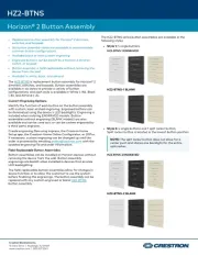
CLTIBN Terminal Blocks
Functional Summary
The Crestron
®
CLTIBN series of terminal blocks with
circuit breakers provide an additional wiring option when
installing Crestron CLXI-series modules in a Crestron
CAENIB automation enclosure. CLTIBN terminal blocks
feature 10A type “C” load-side breakers that offer
additional circuit protection where desired, or where
required by local electrical codes. CLTIBN terminal
blocks ship separately from their corresponding CLXI
modules to permit termination of the field wiring to the
CLTIBN prior to installation of the module. Every
CLTIBN includes a door kit and an adhesive circuit label
(for labeling circuits) to be installed on the cover of the
CAENIB enclosure. This door kit allows access to the
circuit breakers located on the CLTIBN without removing
the cover of the CAENIB enclosure.
Crestron Electronics, Inc. Installation Guide – DOC. 6561A
15 Volvo Drive Rockleigh, NJ 07647 (2017315)
Tel: 888.CRESTRON 04.07
Fax: 201.767.7576 Specifications subject to
www.crestron.com change without notice.
Industry Compliance
This product complies with the essential requirements of
all applicable EU directives.
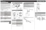
Installation
The terminal block and module must be mounted into a
CAENIB Enclosure by a licensed electrician, in
accordance with all national and local codes.
CAUTION: This equipment is for indoor use only and
needs to be air-cooled. Mount in a well-ventilated area.
The ambient temperature must be 0°C to 40°C (32°F to
104°F). The relative humidity must be 0% to 90% (non-
condensing).
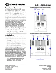
Terminal blocks are installed along the left side of single-
wide enclosures and along the outside edges (left and
right sides) of double-wide enclosures. Modules are
installed along the right side of single-wide enclosures
and side-by-side in the center of double-wide enclosures.
When installing modules and terminal blocks in a double-
wide enclosure, be sure to invert units on the right side so
that they can be properly wired. Refer to the illustrations
shown in the next column and next page when
considering the location of terminal blocks and modules
within an enclosure.
NOTE: For applications where an RCCBO (Residual
Current Circuit Breaker with Overload) is needed, the
CLTIBN’s breaker must be replaced with an RCCBO
(supplied by other). Note that the presence of an RCCBO
requires the CLXI module to be mounted in a different
location to allow for the added size of the new breaker.
Refer to the latest version of the CAENIB Installation
Guide (Doc. 6562) which is available for download from
the Crestron website (
www.crestron.com/manuals).
NOTE: To insure proper fit, terminal blocks and
modules must be installed at the locations indicated in the
latest version of the CAENIB Installation Guide.
NOTE: Modules and terminal blocks must be installed
into the lowest available spaces and continue toward the
top of the enclosure.
Terminal Block & Module Locations (Single-wide Enclosure)
WIRING MODULE
TERMINAL BLOCK
Terminal Block with Breaker Crestron CLTIBN
Terminal Block & Module Locations (Double-wide Enclosure)
GROUNDING STRIP
TERMINAL BLOCKS
WIRING MODULES
NOTE: Unless otherwise indicated, the lighting system
specified in this guide is modular, requiring assembly in
the field by a licensed electrician, in accordance with all
national and local codes.
Terminal Block Installation and
Field Wiring
CAUTION: RISK OF ELECTRIC SHOCK—MORE
THAN ONE DISCONNECT SWITCH MAY BE
REQUIRED TO DE-ENERGIZE THE EQUIPMENT
BEFORE SERVICING.
NOTE: Both left-side and right-side adhesive wiring
labels are provided. The left-side labels are used in both
single and double-wide enclosures. The right-side labels
are only used in double-wide enclosures.
Using the diagram in the next column as reference, install
the terminal block in the CAENIB enclosure.
1. Using a Phillips screwdriver, remove the four
screws securing the cover plate to the CLTIBN
and remove the cover plate.
2. Remove the backing from the left or right
adhesive wiring label. Place the label in the
location where the CLTNIB is to be mounted on
the CAENIB. Align the holes in the label with
the appropriate holes in the CAENIB. Refer to
the latest version of the CAENIB Installation
Guide for information on mounting locations.
CLTIBN Exploded View (CLTIBN-1DELV4 Shown)
3. Use the four supplied self-tapping pan Phillips
screws (8B x ¼-inch (6 mm) length) to secure
the terminal block and the appropriate (left or
right) wiring label to the Crestron Automation
Enclosure. The wiring label lies beneath the
terminal block as shown in the terminal block-to-
module wiring diagrams on page
4.
NOTE: When installed with other terminal blocks,
CLTI-4IND and CLTI-2IND terminal blocks should
be installed at the top of a CAENIB enclosure and
grouped with other CLTI-4IND and CLTI-2IND
terminal blocks.
NOTE: Use copper conductors only – rated 75°C.
4. With the branch circuit breakers and the terminal
block circuit breakers turned off, connect the
circuit feed (LINE and NEUTRAL) and
controlled circuit (LOAD) wires to the terminal
block per the markings provided on the wiring
label (as shown in the terminal block-to-module
wiring diagrams on page
4). Terminal blocks
accept one 2.5 - 6.0 mm
2
wire. Circuit breaker
lugs accept one conductor up to 16 mm
2
. Wires
should be stripped to 12 mm. Tighten terminal
blocks to 1 Nm. Tighten circuit breaker lugs to
1.2 Nm.
5. Grounding terminal blocks are available in the
cabinet for termination of ground wires. Tighten
to 4 Nm (2.5 - 6.0 mm
2
), 4.5 Nm (10.0 mm
2
), or
5.1 Nm (16 - 25 mm
2
).
2 Terminal Block: CLTIBN Installation Guide – DOC. 6561A


Produkt Specifikationer

Mærke: Crestron
Kategori: Ikke kategoriseret
Model: CLTIBN-2DIM8

Har du brug for hjælp?

Hvis du har brug for hjælp til Crestron CLTIBN-2DIM8 stil et spørgsmål nedenfor, og andre brugere vil svare dig