Crestron CLX-PWS75 Manual


Læs gratis den danske manual til Crestron CLX-PWS75 (6 sider) i kategorien Ikke kategoriseret. Denne vejledning er vurderet som hjælpsom af 3 personer og har en gennemsnitlig bedømmelse på 4.8 stjerner ud af 2 anmeldelser. Har du et spørgsmål om Crestron CLX-PWS75, eller vil du spørge andre brugere om produktet?

Side 1/6
CLT- & CLX-PWS75
Functional Summary
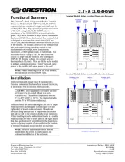
NOTE: Modules and terminal blocks must be installed
into the lowest available spaces and continue toward the
top of the enclosure.
The Crestron
®
75 Watt Power Supply Terminal Block and
Module (CLT-PWS75 and CLX-PWS75, respectively)
They ship separately to permit termination of the field
wiring to the CLT-PWS75 prior to installation of the
CLX-PWS75, as described in this guide. The
to 75 Watts of Cresnet
®
power to Crestron equipment.
The terminal block and module can be mounted in any
Crestron Automation Enclosure (CAEN-Series
Enclosures, refer to the NOTE in the next column). The
terminal block is designed to terminate the circuit feed
(LINE and NEUTRAL) and distribute the power to a
connector on a supplied cable assembly (LOAD) that
connects to the power supply module. The power supply
module operates with an input of 100 to 250 VAC, 2.3A
(maximum). The power supply module has a fuse that
protects the 24 VDC output. If the network power lines
are shorted, the fuse is blown. As a result, the NET
POWER LED extinguishes.
Terminal Block & Module Locations (Single-wide Enclosure)
GROUNDING
TERMINAL
BLOCK
MODULETERMINAL
BLOCK
Regulatory Compliance
This product is Listed to applicable UL Standards
and requirements by Underwriters Laboratories Inc.
Terminal Block & Module Locations (Double-wide Enclosure)
MODULE
TERMINAL BLOCK
(RIGHT)
GROUNDING TERMINAL BLOCKS
TERMINAL BLOCK
(LEFT)
MODULE
Installation
The terminal block and module must be mounted into a
Crestron Automation Enclosure by a licensed electrician,
in accordance with all national and local codes.
CAUTION: This equipment is for indoor use only and
needs to be air-cooled. Mount in a well-ventilated area.
The ambient temperature must be 32°F to 104°F (0°C to
40°C). The relative humidity must be 0% to 90% (non-
condensing).
Crestron Electronics, Inc. Installation Guide – DOC. 6348B
15 Volvo Drive Rockleigh, NJ 07647 (2012603)
Tel: 888.CRESTRON 11.11
Fax: 201.767.7576 Specifications subject to
www.crestron.com change without notice.
Terminal blocks are installed along the left side of single-
wide enclosures and along the outside edges (left and
right sides) of double-wide enclosures. Modules are
installed along the right side of single-wide enclosures
and side-by-side in the center of double-wide enclosures.
When installing modules and terminal blocks in a double-
wide enclosure, be sure to invert units on the right side so
that they can be properly wired. Refer to the illustrations
of terminal blocks and modules within an enclosure.
Terminal Block & Module Crestron CLT- & CLX-PWS75
Terminal Block Installation and
Field Wiring
Wiring Diagram of the Terminal Block to the Feed and
Load(s)(Single-wide and Left Side Double-wide Enclosures)
AREA FOR MODULE
LOCATION LABEL
TERMINAL
BLOCK
WIRING LABEL
GROUND
NEUTRAL
LINE
FROM 15 OR 20 AMP
CIRCUIT BREAKER
TO BLACK LEAD OF
CABLE ASSEMBLY
TO WHITE LEAD OF
CABLE ASSEMBLY
TO GREEN LEAD OF
CABLE ASSEMBLY
CAUTION: RISK OF ELECTRIC SHOCKMORE
THAN ONE DISCONNECT SWITCH MAY BE
REQUIRED TO DE-ENERGIZE THE EQUIPMENT
BEFORE SERVICING.
NOTE: Both left-side and right-side adhesive wiring
labels are provided. The left-side labels are used in both
single and double-wide enclosures. The right-side labels
are only used in double-wide enclosures.
1. Remove the backing from the left or right
adhesive wiring label.
2. Apply the adhesive label by aligning the holes in
the label with the holes on the Crestron
Automation Enclosure where the terminal block
is to be mounted. The wiring label lies beneath
the terminal block as shown in the two wiring
diagrams on this page.
Wiring Diagram of the Terminal Block to the Feed and
Load(s)(Right Side Double-wide Enclosures)
TERMINAL
BLOCK
WIRING LABEL
LINE
FROM 15 OR 20 AM
P
CIRCUIT BREAKER
NEUTRAL
GROUND
AREA FOR MODULE
LOCATION LABEL
TO GREEN LEAD OF
CABLE ASSEMBLY
TO BLACK LEAD OF
CABLE ASSEMBLY
TO WHITE LEAD OF
CABLE ASSEMBLY
3. Use the two supplied self-tapping pan Phillips
screws (8B x 1/4 length) to secure the terminal
block to the Crestron Automation Enclosure.
NOTE: Use copper conductors only rated
75°C.
4. With the circuit breaker turned off, connect the
circuit feeds (LINE, NEUTRAL, and GROUND)
to the terminal block per the markings provided
on the wiring label (as shown in the following
diagram). Terminal blocks accept one 14 - 10
AWG wire. Wires should be stripped to 1/2 inch.
Tighten terminal blocks to 9 in-lbs.
NOTE: LINE and NEUTRAL lines can be
jumped to other terminal blocks in the
enclosure.
5. Grounding terminal blocks are available in the
cabinet for termination of ground wires. Tighten
to 35 in-lbs. (14 10 AWG).
Module Installation
CAUTION: The module contains electrostatic sensitive
devices (ESDs); unit must be handled from metal chassis
do not touch PC board or components.
6. Connect each wire from the connector assembly
to the terminal block. Each wire is the same
color as the terminal to which it should be
connected. Wires are pre-stripped to 1/2 inch.
Tighten to 9 in-lbs.
NOTE: Modules are to be installed after enclosure has
been completely wired. Refer to the terminal block
installation procedure on the top of the page for details.
7. Test the circuit for electrical faults by turning on
the circuit breaker and checking that the breaker
does not trip and that power is supplied to the
connector of the cable assembly.
1. Use the four supplied self-tapping screws (8B x
1/4 length) to secure the module to the enclosure.
2. If the module is being installed below another
module within the enclosure, attach the supplied
module interconnect cable between the two
2
Terminal Block & Module: CLT- & CLX-PWS75 Installation Guide – DOC. 6348B


Produkt Specifikationer

Mærke: Crestron
Kategori: Ikke kategoriseret
Model: CLX-PWS75

Har du brug for hjælp?

Hvis du har brug for hjælp til Crestron CLX-PWS75 stil et spørgsmål nedenfor, og andre brugere vil svare dig