Crestron MPC-M20-B-T Manual
Crestron
Trådløs oplægsholder
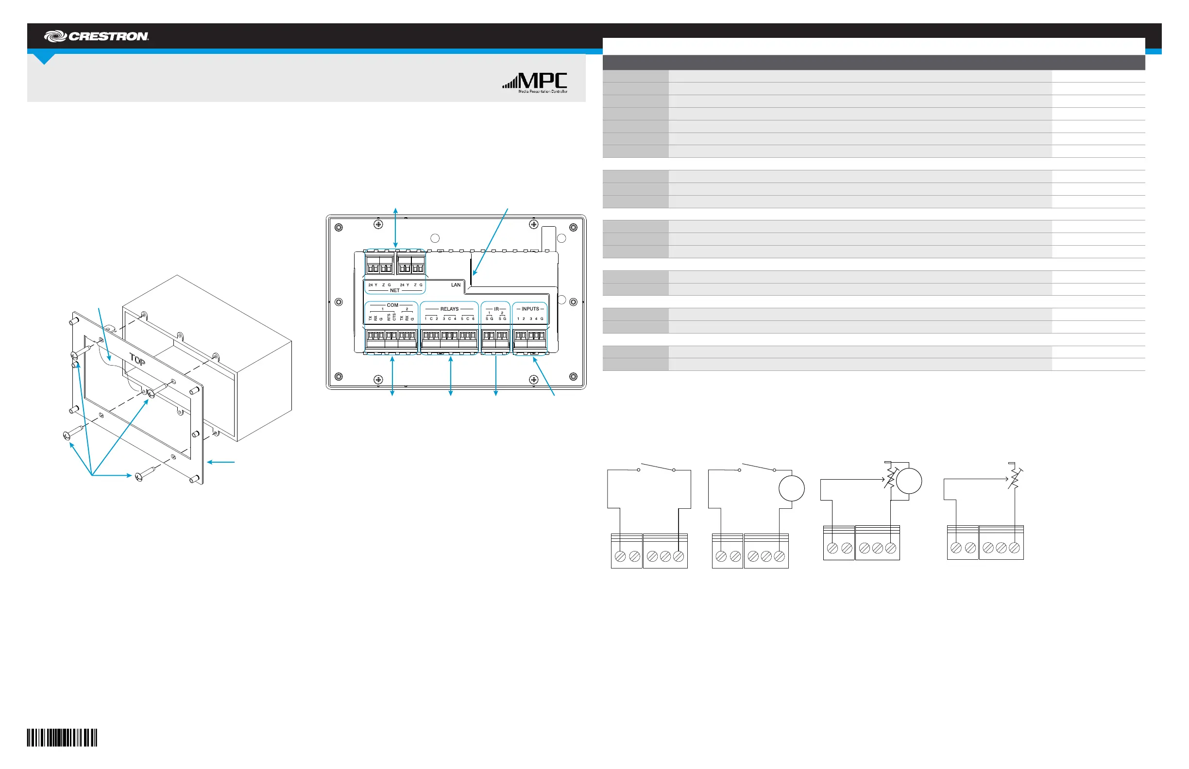
MPC-M20-B-T
| Mærke: | Crestron |
| Kategori: | Trådløs oplægsholder |
| Model: | MPC-M20-B-T |
| Bredde: | 170.2 mm |
| Dybde: | 56.7 mm |
| Højde: | 114.3 mm |
| Vægt: | 610 g |
| Relativ luftfugtighed ved drift (H-H): | 10 - 90 % |
| Ethernet LAN-porte (RJ-45): | 1 |
| Ethernet LAN: | Ja |
| Driftstemperatur (T-T): | 0 - 40 °C |
| Ethernet LAN-datahastigheder: | 10, 100 Mbit/s |
| Intern hukommelse: | 32 MB |
| Volumenkontrol: | Dreje |
| Husmateriale: | Plast |
| Knapper med baggrundsbelysning: | Ja |
| Webbaseret administration: | Ja |
| Knap til nulstilling: | Ja |
| LED-indikatorer: | Activity, Link |
| Kan monteres på væggen: | Ja |
| Intern hukommelsestype: | SDRAM |
| Antal knapper: | 15 |
| Flashhukommelse: | 8 MB |
| Fuld duplex: | Ja |
| Husets farve: | Sort |
| Varmeafgivelse: | 17 BUT/t |
| RS-232-porte: | 1 |
| USB porttype: | USB Type-B |
| Statisk IP: | Ja |
| Processor arkitektur: | ColdFire |
| Strømforsyning inkluderet: | Ja |
| Fjernbetjening (IR) udgang: | 1 |
| Fjernbetjeningens transmissionsafstand: | 15 m |
| Lyssensor: | Ja |
| Brugerdefinerbare knapper: | Ja |
| Infrarødt (IR) frekvens rækkevidde: | 36 - 38 kHz |
| D-pad: | Ja |
| Udvekslingsprotokoller: | IP, DHCP, DNS, SSL, TCP/IP, UDP/IP, CIP, SMTP, SNMP |
| Ekstern strømforsyning: | Ja |
| Hårde knapper: | Ja |
| Antal indbyggede relæer: | 2 |
| Nulstil typer: | Nulstilling af hardware |
| Volumenkontrolknap: | Ja |
| NVRAM-kapacitet: | 256 KB |
| Strømterminalblok: | 2 |
Har du brug for hjælp?
Hvis du har brug for hjælp til Crestron MPC-M20-B-T stil et spørgsmål nedenfor, og andre brugere vil svare dig
Trådløs oplægsholder Crestron Manualer
21 August 2024

21 August 2024
20 August 2024
19 August 2024
19 August 2024
Trådløs oplægsholder Manualer
- Genius
- Procare
- Kensington
- Epson
- Planet
- Edimax
- BenQ
- Wentronic
- Logitech
- Intellinet
- ByEasy
- Iogear
- SMK-Link
- StarTech.com
- V7
Nyeste Trådløs oplægsholder Manualer

20 Februar 2025
31 December 2025
19 December 2024
19 December 2024

17 December 2024

17 December 2024

17 December 2024

17 December 2024

17 December 2024

17 December 2024