@crown
®
* System
®
Quick Reference
IQ-DRN16 DRONE
screws. At the rear of the cage a terminal
board (“T-board”) is used to provide connec-
tion to external input and output devices. The
T-board for the Drone is shown on the follow-
ing page.
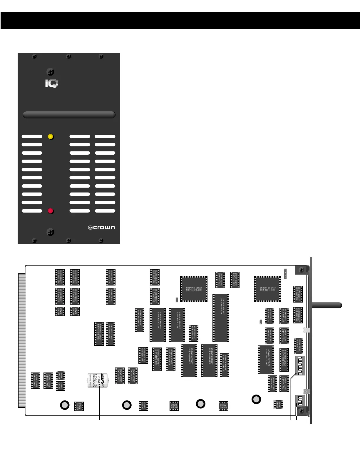
Front Panel
The front panel for the Drone is shown to the
left. A DSPI indicator lights up to indicate that
digital information addressed to that unit is
being received. It also has a power indicator
showing that the unit is powered by +12 VDC.
A. Baud Switches
SW1 on the Drone module is a four position
DIP switch used to set the RS232/422 baud
rate. The Drone supports from 1200 to 38400
baud. Note: Some PCs do not support greater
than 9600 baud.
B. IQ Address Switches
Drones, like all IQ System components, must
have a valid IQ Address in order to commu-
nicate a computer or other system compo-
nents. A valid address is an address ranging
from 1 to 250, with no other Drones having
the same IQ Address in the same system.
C. Battery Backup
The battery on the Drone allows it to main-
tain its programming for up to 30 days after
Overview
The Drone is a general purpose IQ command
and control module. It accepts a variety of
types of external stimuli and converts them
into commands for various other IQ compo-
nents in the system. It is a modular unit de-
signed for mounting in the IQ-CAG Card
Cage. It operates on a nominal +12 VDC, and
includes 30 day battery backup. It is
equipped to communicate directly with a
computer via female DB9 serial port (RS232/
RS422). As a system interface it supports two
Crown Bus serial data loops. It is pro-
grammed via graphic objects or text oriented
screens in the IQ-MSD Turbo 1.2 (or higher)
program.
IQ-CAG Card Cage Installation
The Drone designed for easy installation into
the IQ Card Cage. The IQ-CAG is a four rack
space cage which is segregated into 14 1.25
inch widths. The Drone is three widths (3.75
inches wide). The IQ-LPS +12 VDC Linear
Power Supply is another Card Cage unit, and
provides power supply voltage for Card Cage
components, including the Drone. If an IQ-
LPS is not used, another suitable supply such
as an adaptor or battery is required. Compo-
nents designed to mount in the IQ-CAG are
modular in construction. They slide into the
cage on rails, and are held in place by small
DRONE
POWER
1718 W. Mishawaka Rd.
Elkhart, IN 46517 U.S.A.
DSPI
12
3
4
5
6
7
8
A
12
3
4
BC
DRONE MODULE CIRCUIT BOARD
IQ-DRN16 DRONE