DBX PB48 Manual


Læs gratis den danske manual til DBX PB48 (5 sider) i kategorien Ikke kategoriseret. Denne vejledning er vurderet som hjælpsom af 19 personer og har en gennemsnitlig bedømmelse på 4.2 stjerner ud af 10 anmeldelser. Har du et spørgsmål om DBX PB48, eller vil du spørge andre brugere om produktet?

Side 1/5
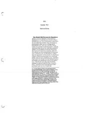
PB-48 Patchbay
INTRODUCTION
UNDERSTANDING PATCHBAYS AND THE PBdbx -48
(A) Normalled Patchbay (B) Half-Normalled [Mult-ed] Patchbay
(C) Half-Normalled Patchbay (D) De-Normalled Patchbay
[With Rear-Panel Normal Connection Broken]
Figure 1: Normalled, Half-Normalled and De-Normalled Patchbay Operation
SIGNAL FLOW
FRONTBACK
SOURCE 1
OUT
IN
IN
OUT
BACK
SIGNAL FLOW
FRONT
TO LOAD 2
TO LOAD 1
SOURCE
2
SOURCE
OUT
IN
OUT
BACK
SIGNAL FLOW
FRONT
TO LOAD 1
TO LOAD 2
SOURCE
IN
OUT
BACK
SIGNAL FLOW
FRONT
TO LOAD
The PB-48 is shipped from the factory with its circuit boards installed for
half-normalled patchbay operation. means that audio signalNormalled
automatically flows between a vertical pair of patchbay jacks without the
need for patchcords (see Figure 1-A). Normalled patchbays may be half-
normalled or full-normalled. In the half-normalled PB-48, each rear panel
upper jack is respectively normalled to the jack directly below it as long
as nothing is plugged into the lower front-panel jack. Half-Normalled
means that pluggging into the upper front-panel jack does not break the
connection between the upper and lower rear-panel jacks, while plug-
ging into the lower front panel jack breaks the connection (see Figures
1-B adn 1-C). Note: A full-normalled patch bayÕs rear-panel connections
are broken when plugging into either front-panel jack.
A simple example of using half-normalled operation: connect a mixerÕs
monitor out to one of the PB-48Õs rear panel upper jacks, then connect
the rear panel jack directly below it to a power amplifier. The ÒNormalledÓ
signal will flow from the mixer monitor out to the power amplifier, and will
only be broken when a connection is made to the corresponding front
panel lower jack.
Congratulations on purchasing the dbx PB-48 rackmountable patchbay.
The PB-48 features 48 front panel patchpoints and 48 rear panel patch-
points, from 24 user-adjustable board assemblies that can be configured
forHalf-Normalled or De-Normalled patchbay operation without soldering
or cutting wires. The PB-48 is a rugged, noise-free, patchbay designed
to serve all your patchbay needs, from providing clear and easy access
to your mixer and other studio gear, to reducing the wear and tear on
their jacks, to facilitating quick and precise re-routing of devices within
your studio setup. PB-48 patchbay jacks accept balanced TRS or unbal-
anced TS standard audio 1/4Ó plugs.
We recommend that you take a moment and read through this instruc-
tion sheet as it provides information that will assist you in using your
patchbay to its fullest. Explanations of standard patchbay jargon, with
plenty of pictures, are included to help demystify common patchbay
points of entanglement and clear up any misunderstandings you might
have. Examples, suggestions and tips are provided as a starting point
only. Experiment with different setups, so that you find the setup that
best fits your system.
1
(A) Unscrew rear panel nut and save it. (B) Push down on rear lower jack, and snap board out
(C) Keeping circuit board component side facing you, (D) Angle board in (front lower jack to lower front hole), and
rotate the board 180û. push rear upper jack (in and up) to snap board into place.
(E) Re-tighten upper jack with nut from step A.
Figure 2: De-Normalled Configuration Steps [To Re-Normalize, repeat steps]
TIGHTEN
FRONT
PUSH IN AND UP FRONT
BOARD AFTER 180 ROTATION
(logo on bottom)
°
°
°
°°
PUSH
HERE
FRONT
UNSCREW
FRONT
The front panel upper jacks in a Half-Normalled/Normalled patchbay are
usually considered to be outputs because each front panel upper jack is
wired directly to its corresponding rear panel upper jack, where the audio
connection is initiated (see Figure 1-B). For example, connecting a head-
phone to the front panel upper jack allows you to Òlisten inÓ to the signal
from the corresponding rear jack. This setup is sometimes called a Mult-
ed patchbay, because the patchbay simultaneously routes the rear panel
signal (i.e., signal fed to the rear upper jack) to multiple points: one out-
put to the rear panel lower jack and one output at the front panel upper
jack. A possible setup might have a mono mix sent to the rear upper jack,
the routed signal at the lower rear jack fed to the power amp, and the
routed signal at the front panel upper jack connected to a tape recorder
input for a mono tape mix.
The front panel lower jacks in a Half-Normalled/Normalled patchbay are
called inputs because they actually interrupt the signal fed into the corre-
sponding rear panel upper jack and provide a new input to the rear panel
lower jack (Figure 1-C). For example, inserting a DAT recorder signal into
the front panel lower jack routes the tape signal directly to the corre-
sponding rear panel lower jack. Note, however, that the front panel upper
jack retains the signal from the rear panel upper jack.
The front panel lower jack input can also be used to alter its correspond-
ing rear panel upper jack input when the board assembly is correctly
patched to a signal processor (e.g., an equalizer, compressor, gate, etc.).
Start with a mixer and amp connected to one vertical pair of the patch-
bayÕs rear panel jacks, as described before. Then, connect the front
panel upper patchbay jack (which has the mixerÕs output signal) to the
processorÕs input, and connect the processorÕs output to the front panel
lower jack input which feeds the amp.
To connect devices like effects or signal processors directly to the PB-
48Õs rear panel jacks, so that they are accessible through a vertical pair
of front panel patchpoints, the PB-48 must be De-Normalized (see Figure
1-D for example and Figure 2 for customization instructions).
In a (or ) patchbay, each front panel jackDe-Normalled Non-Normalled
is routed directly and only to the corresponding rear panel jack (i.e., first
upper front to first upper rear, first lower front to first lower rear, etc.). De-
Normalled operation is especially useful with effects devices or other
input/output devices because its ÒstraightÓ signal flow helps reduce feed-
back or the chance of oscillations through signal loops.
Although a De-Normalled circuit board eliminates Mult-ed outputs, the
number of possible ÒstraightÓ signal connections is increased. For exam-
ple, to provide access to all the inputs of a 16-channel mixer, connect the
first eight pairs of the patchbayÕs rear panel jacks respectively to the 16
mixer inputs. Now, plugging a synthesizer into one of the front panel
patchpoints routes the synthesizer signal directly to the corresponding
mixer input. Note that all of this can be accomplished using only 1/3 of
the patchbay.


Produkt Specifikationer

Mærke: DBX
Kategori: Ikke kategoriseret
Model: PB48

Har du brug for hjælp?

Hvis du har brug for hjælp til DBX PB48 stil et spørgsmål nedenfor, og andre brugere vil svare dig


Ikke kategoriseret DBX Manualer

DBX

DBX 120X Manual

9 Juni 2025
DBX

DBX 120XP Manual

8 Juni 2025
DBX

DBX 120A Manual

7 Juni 2025
DBX

DBX SC 32 Manual

30 December 2025
DBX

DBX SC 64 Manual

30 December 2025
DBX

DBX PS6 Manual

14 November 2024
DBX

DBX PMC16 Manual

14 November 2024
DBX

DBX 676 Manual

10 September 2024
DBX

DBX DriveRack 220i Manual

4 September 2024
DBX

DBX DriveRack PX Manual

4 September 2024

Ikke kategoriseret Manualer

Nyeste Ikke kategoriseret Manualer