DeLonghi PAC EX UV Carelight Manual
DeLonghi
Klimaanlæg
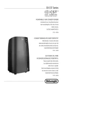
PAC EX UV Carelight

| Mærke: | DeLonghi |
| Kategori: | Klimaanlæg |
| Model: | PAC EX UV Carelight |
Har du brug for hjælp?
Hvis du har brug for hjælp til DeLonghi PAC EX UV Carelight stil et spørgsmål nedenfor, og andre brugere vil svare dig
Klimaanlæg DeLonghi Manualer
6 September 2025
6 September 2025
30 August 2025

10 Januar 2025

24 Maj 2024

12 Maj 2024

29 April 2024

11 April 2024

6 April 2024

21 Marts 2024
Klimaanlæg Manualer
- Brandson
- Perfect Aire
- Matsui
- Uniprodo
- ARGO
- Climadiff
- Optimea
- GE
- Xiaomi
- Honeywell
- Airrex
- Omega
- AlpicAir
- Commercial Cool
- Dimplex
Nyeste Klimaanlæg Manualer
4 November 2025

4 November 2025

4 November 2025

4 November 2025

4 November 2025

4 November 2025
3 November 2025
2 November 2025
1 November 2025
1 November 2025