Delta 5COM-CN-016CS Manual
Læs gratis den danske manual til Delta 5COM-CN-016CS (8 sider) i kategorien Bruseanlæg. Denne vejledning er vurderet som hjælpsom af 8 personer og har en gennemsnitlig bedømmelse på 4.7 stjerner ud af 4.5 anmeldelser.
Har du et spørgsmål om Delta 5COM-CN-016CS, eller vil du spørge andre brugere om produktet?
Produkt Specifikationer
| Mærke: | Delta |
| Kategori: | Bruseanlæg |
| Model: | 5COM-CN-016CS |
Har du brug for hjælp?
Hvis du har brug for hjælp til Delta 5COM-CN-016CS stil et spørgsmål nedenfor, og andre brugere vil svare dig
Bruseanlæg Delta Manualer


Bruseanlæg Manualer
- Fala
- Juno
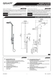
- Graff
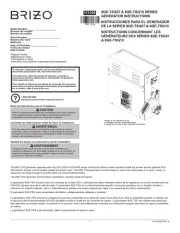
- Brizo
- Haws
- BMI
- Thermomate
- Panasonic
- Symmons
- Schütte
- Miomare
- Sani-Lav
- ECOstyle
- Omnires
- Curaqua
Nyeste Bruseanlæg Manualer