Wichtiger Hinweis!
Es wird empfohlen, dieses Gerät im privaten
Bereich, z.B. Beleuchtung für Hofeinfahrten,
Garagen, Schaufenster usw. einzusetzen.
Für den industriellen Einsatz und öffentliche
Einrichtungen, wie Straßenbeleuchtung,
Warnbeleuchtungen usw., empfehlen wir un-
seren Dämmerungsschalter Typ DÄ 565 15.
Das Gehäuse ist sorgfältig zu verschließen, um das
Eindringen von Wasser zu verhindern.
Achtung!
Bei Feineinstellung des Dämmerungsschalters, d. h.
gewünschter Schaltpunkt entspricht den momenta-
nen Lichtverhältnissen, muss beachtet werden, dass
für jede Einstellung die Ein-Aus-Schaltverzögerungs-
zeit von ca. 30 sec. abgewartet werden muss.
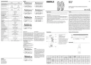
4. Technische Daten
Bestell-Bez. 565 07 S
Nennspannung 220 V +10%/–15%
50 Hz
Kontakt 1 Schließer
Nennstrom *) 10 A/250 V~
Einstellbereich**) ca. 1 bis 100 Lux
Schaltverzögerung Ein/Aus ca. 30 sec.
Umgebungstemperatur –30 bis +55 °C
Schutzart IP 54
Bemessungsstoßspannung 2,5 KV
Temperatur für die Kugel-
druckprüfung 75°C
Spannung und Strom für
Zwecke der EMV-Stör-
aussendungsprüfungen 230 V; 0,1 A
*) Glühlampen max. 1600 W
Quecksilberlampe max. 1000 W
Natriumlampe max. 200 W
Leuchtstofflampen
unkompensiert max. 1000 W
kompensiert max. 600 W
in Duo-Schaltung max. 2000 W
**) Der normale Arbeitsbereich eines Dämmerungs-
schalters liegt beim Einsatz im Freien zwischen ca. 7-
30 Lux. Mit dem Einstellbereich von ca. 1-100 Lux ist
eine exakte Einstellmöglichkeit für diesen Bereich
gegeben.
5. Funkentstörung 3
Der Dämmerungsschalter ist gemäß VDE 0875
nach Funkstörgrad N funkentstört und entspricht
der EG-Richtlinie 82/499 EWG.
6. Funktion
Bei heller Beleuchtung ist der Relaiskontakt geöff-
net. Unterschreitet die Beleuchtung den einge-
stellten Lichtwert, zieht das Relais verzögert an.
Wird der Lichtwert wieder überschritten, fällt das
Relais verzögert ab.
Die Verzögerung vermeidet ein unkontrolliertes
Schalten durch kurzzeitiges Störlicht (Autoschein-
werfer, Blitze usw.).
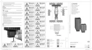
7. Plombierung des Gehäuses
1. Rechte obere Deckelschraube ersetzen durch
beiliegende Plombierschraube (mit Querloch)
2. Plombierdraht durch Kanal im Deckel und
Plombierschraube ziehen und Plombe setzen.
U 468 931 001 437-03
Notice de
montage et d’utilisation
Interrupteur crépusculaire
Type 565 07 S
U 468 931 001 437-03
Installation and
operating instructions
Twilight switch
Type 565 07 S
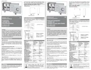
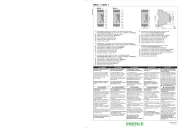
1. Montageanleitung
Der Dämmerungs-
schalter sollte nur
an ebenen, senkrech-
ten und in etwa nach
Norden ausgerichte-
ten Flächen (Haus-
wänden) montiert
werden und möglichst
nicht dem direkten
Sonnenlicht ausge-
setzt sein.
Das Gerät sollte nicht unter 3 m Höhe montiert
werden und darf auch nicht im Schatten von Bäu-
men oder Sträuchern sein. Der Dämmerungs-
schalter schaltet sonst morgens zu spät aus!
Die Befestigungslöcher (4,5 mm ∅) sind nach Ab-
nahme des Gehäusedeckel (4 Schrauben) zugäng-
lich. Achtung: Das Sichtfenster darf nicht durch das
einzuschaltende Licht beleuchtet werden!
2. Anschluss
Die Kabelzuführung (eine Leitung mit max. 3 x 2,5
mm2) darf nur von unten her in fester Verlegung
erfolgen. Nur dann ist eine wasserdichte Montage
gewährleistet. Das Durchschleifen einer Schutzlei-
terverbindung ist nicht möglich.
Dazu ist das Gehäuse
unterhalb der Klem-
men 3, 4, 5 auszubre-
chen und der Gummi-
verschluss einzusetzen.
Der Anschluss erfolgt
gemäß dem Schaltbild
auf der Elektronikab-
deckung.
3. Einstellen der Lichtempfindlichkeit
Der Ansprechwert des Dämmerungsschalters ist
ab Werk auf ca. 10 Lux eingestellt. Andere An-
sprechwerte (zwischen 1-100 Lux) können bei ab-
genommenem Deckel mit einem Schraubendre-
her eingestellt werden. Auf der Skala der Elektro-
nikabdeckung sind die verschiedenen Luxwerte
ersichtlich. Diese Werte gelten jedoch nur bei ge-
schlossenem Gehäusedeckel!
Die Elektronikabdeckung darf nicht entfernt wer-
den, da sonst keine einwandfreie Funktion ge-
währleistet ist.
ACHTUNG
Das Gerät darf nur durch einen Fachmann instal-
liert bzw. eingesetzt werden. Dabei sind die beste-
henden Sicherheitsvorschriften zu beachten.
Dieser unabhängig montierbare elektronische
Dämmerungsschalter dient zum Schalten von Be-
leuchtungseinrichtungen. Er arbeitet nach der
Wirkungsweise 1 C.
1. Installation Notes
The twilight switch
should be mounted
only on a smooth,
vertical surface, ex-
posed to the north
(house walls) and
preferably avoiding
direct sunlight.
The device should be
mounted at a mini-
mum height of 3 me-
tres. Please make sure that it is not mounted un-
der the shadow of trees or shrubs, as this would
cause it to switch off too late in the morning.
The fixing holes (diam. 4.5 mm) can be accessed
after removing the cover (4 screws). Warning: the
photocell opening should not be reached by the
light controlled by the twilight switch.
2. Wiring
Cable entry (one cable with max. 3 x 2.5 mm2) must
be from below with the wires firmly secured. Only
in this way can the water tightness of the housing
be ensured. Looping through of any earth connec-
tion will not be possible. To do this, the housing
must be pressed out below the terminals 3, 4 and 5
and the rubber grommets fixed. Make all connec-
tions by following the wiring diagram on the elec-
tronic equipment cover of the device.
3. Setting light sensitivity
The tripping value is factory set to approx. 10 Lux.
Other values from 1 to 100 Lux can be set by
means of a screwdriver after removing the front
cover. The photocell Lux range is clearly marked
on the electronic equipment cover. However, such
values only apply when the housing cover is
closed.
ATTENTION
The device should only be installed and moun-
ted by a qualified technician, in compliance with
applicable safety regulations in force.
This electronic twilight switch is used for swit-
ching light equipment, it operates according
type 1C
Warning!
When fine tuning the twilight switch by setting the
desired switching point to the current lighting condi-
tions, please bear in mind that for each adjustment
to become effective, you should wait for the switch
on/off delay time (approx. 30 sec.) to elapse.
4. Technical data
Type 565 07 S
Operating voltage 220V +10%/-15% 50 Hz
Contact 1 n/o
Current rating *) 10 A/ 250 V~
Operating range**) approx. 1 – 100 Lux
On/off delay time approx. 30 sec.
Ambient temperature –30 to +55 °C
Protection rating IP 54
Rated impulse voltage 2.5 KV
Brinell test temperature 75°C
Voltage and current for
EMC emitted
interference testing 230 V; 0,1 A
*) Incandescent lamps max. 1600 W
Mercury lamp max. 1000 W
Sodium lamp max. 200 W
Fluorescent lamps
uncompensated max. 1000 W
compensated max. 600 W
dual-lamp circuit max. 2000 W
**) The regular operating range of a twilight
switch intended for outdoor use is approx. 7-
30 Lux. Thanks to a wide setting range (approx.
1-100 Lux), this device can be set in an ex-
tremely precise way to meet the specific appli-
cation requirements.
5. Suppression
The twilight switch is suppressed to VDE 0875 class
N, and is built in compliance with the European Di-
rective 82/49/EEC.
6. Operation
In full light the relay contact is open. When the
light level falls below the set value the relay is ex-
cited after the delay time. When the light level ex-
ceeds the set value, the relay drops out after the
delay time. The delay is included to ensure that the
relay is not energised by short duration sources of
light, e.g. car headlamps, lightning flashes etc.
7. Sealing the housing
1. Remove the top right cover screw and replace it
with the seal screw supplied which has a trans-
verse hole.
2. Pass the seal wire through the channel in the
cover and through the seal screw. Crimp the
lead seal in the usual way.
NOTE
The 565 07 is intended mainly for use in the pri-
vate sector e.g. driveways, garages, porches etc.
For industrial and commercial applications such
as street lighting, filling stations, underpasses
etc. the twilight switch type 565 15 is considered
more suitable.
1. Instructions de montage
L'interrupteur crépus-
culaire doit être mon-
té sur une surface pla-
ne verticale, située au
nord, non exposée au
rayonnement solaire.
Cet appareil ne doit pas
être installé à moins de 3
mètres du sol ni à l’ombre
d’arbres ou d’arbustes. Sinon l’interrupteur cré-
pusculaire s’éteint trop tard le matin.
Les trous de fixation ( 4,5 mm) sont accessibles∅
en enlevant le couvercle (4 vis).
Attention: l’orifice du couvercle, permettant le
contrôle de la luminosité, ne doit pas être éclairé
par la lumière commandée par l’interrupteur cré-
pusculaire.
2. Raccordement
Le raccordement du câble électrique (un cable de
max. 3 x 2,5 mm2) doit impérativement se faire par
le bas de l’appareil pour garantir l’étanchéité, le fil
de terre ne peut former de boucle.
Il faut évider le boîtier sous les bornes 3, 4, 5 et
mettre le joint caoutchouc en place.
Le raccordement élec-
trique se fait confor-
mément au schéma
marqué sur la plaque
de recouvrement de
l’électronique.
3. Réglage de la sensibilité
de luminosité
Le seuil d’enclenchement de l’interrupteur cré-
pusculaire est réglé en usine à 10 Lux env. ce qui
correspond à la valeur la plus usitée. D’autres
seuils peuvent être réglés (de 1 à 100 Lux) au
moyen d’un tournevis, une fois le couvercle enle-
vé.
La plage de réglage est indiquée sur la plaque de
recouvrement de l’électronique. Les valeurs ne
sont néanmoins valables que lorsque le couvercle
est à nouveau mis en place. Cette plaque de re-
couvrement de l’électronique ne doit jamais être
enlevée pour pouvoir garantir un fonctionnement
correct.
Le boîtier doit être clos soigneusement, pour évi-
ter l’introduction de l’humidité.
ATTENTION
L'appareil ne doit être installé et monté que par un
professionnel qualifié et conformément aux normes
de sécurité en vigueur.
Cet interrupteur crépusculaire électronique est desti-
né à l'utilisation d'équipements d'éclairage et fonc-
tionne selon le type 1C.
IMPORTANT:
L’interrupteur crépusculaire de type 565 07 est pré-
vu pour un usage domestique, tel que: éclairage de
rampe de garage, de vitrines, de cours etc.
Pour un usage industriel et publique, tel que éclai-
rage routier, panneaux indicateurs, nous vous re-
commandons notre appareil de type 565 15.
Irrtum und Änderungen vorbehalten Errors possible/subject to alterations Sous réserve d’erreurs
U 468 931 001 437-03
Montage- und
Bedienungsanleitung
Dämmerungsschalter
Typ 565 07 S
A n!ttentio
Lors de la mise au point de l’interrupteur crépusculaire,
c’est-à-dire lorsqu’on fait correspondre le seuil de régla-
ge avec les conditions de luminosité du moment, il faut
tenir compte que pour chaque réglage, on doit attendre
que la temporisation à l’enclenchement et au déclenche-
ment (30 sec. environ) soit écoulée.
4. Caractéristiques techniques
Type 565 07 S
Tension nominale 220 V +10%/-15%
50 Hz
Type de contact 1 contact nor-
malement ouvert
Courant nominal *) 10 A/ 250 V,
50 Hz résistif
Plage de réglage**) env. 1 – 100 Lux
Temporis. Enclench./Déclench. env. 30 secondes
Température ambiante
admissible –30° à +55 °C
Classe de protection IP 54
Surtension transitoire
dimensionnée 2,5 KV
Température d’essai Brinell 75°C
Tension et courant de
contrôle de compatibilité
électromagnétique 230 V; 0,1 A
*) Lampes à incandescence max. 1600 W
Lampe à mercure max. 1000 W
Lampe à sodium max. 200 W
Lampes fluorescentes
non compensées max. 1000 W
compensées max. 600 W
circuit à deux lampes max. 2000 W
**) La plage de fonctionnement normale d’un interrup-
teur crépusculaire installé en plein air est comprise
entre 7 et 30 Lux environ. La plage de réglage compri-
se entre 1 et 100 Lux, permet un réglage très précis de
cet appareil dans ce domaine d’utilisation.
5. Anti-parasitage
L’interrupteur crépusculaire est anti-parasite selon
VDE 0875 classe N ; il est conforme à la directive
européenne 82/499/CEE.
6. Fonctionnement
Le contact relais est ouvert en cas de haute lumi-
nosité. Lorsque la luminosité descend au-dessous
du seuil réglé, le relais s’excite après la temporisa-
tion. Lorsque la luminosité dépasse à nouveau le
seuil, le relais revient à sa position de repos, tou-
jours après la temporisation. Cette temporisation
sert à éviter l’enclenchement intempestif de l’ap-
pareil causé par des sources de luminosité de
courte durée (phares de voitures, éclairs, etc.)
7. Plombage du boîtier
1. Remplacer la vis en haut à droite du couvercle
par la vis de plombage fournie (avec perçage
transversal).
2. Faire passer le fil de plombage à travers le perç-
age de la vis de plombage et l’évidement pré-
sent dans le couvercle. Installer le plomb à scel-
ler.