ELIVED YD5011 Manual


Læs gratis den danske manual til ELIVED YD5011 (2 sider) i kategorien Højtalerbeslag. Denne vejledning er vurderet som hjælpsom af 2 personer og har en gennemsnitlig bedømmelse på 3.5 stjerner ud af 1.5 anmeldelser. Har du et spørgsmål om ELIVED YD5011, eller vil du spørge andre brugere om produktet?

Side 1/2
05
05
Safety Caution
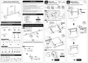
INSTALLATION INSTRUCTION
DWD704_US1.0
If you have any questions, please feel free to contact Customer Service
via Amazon before returning.
x2pcs
x1pcs
Connecting Plate
01
02
Supplied Parts and Hardware
NOTE: Not all parts and hardware included will be used.
x2pcs
Hook
04
x2pcs
Support Plate
03
Soundbar & Bracket
×2
Soundbar Screws
×2
M5×15mm
×2
M6×15mm
×2
Long Nut
×2
×2
Screws
×8
Connecting Screws Washers
M4×15mm
Ф6mm
Concrete Wall Anchor
Ф10×61mm
Lag Bolt
ST6x60mm
Wall
×2
B
×2
A
Must Check Before Getting Started
VESA Pattern :(W × H)
MIN: 200mm × 100mm / 4" × 3"
MAX: 800mm × 300mm / 32" × 12"
W
H
TV
Spacers
H10mm
×4
E
Spacers
H2.5mm
×6
F
Washers
×4
G
Ф6mm
Philips Screws
×4
C
M8 x 25mm
Philips Screws
×4
D
M8 x 45mm
Philips Screws
M6 x 15mm
A
×4
Philips Screws
M6 x 25mm
B
×4
M5×8mm M3×8mmM3
±90°
MAX: 32.5"(825mm)
33.9"(860mm)
17.7"
(450mm)
6.5"
(164mm)
±90°
VESA:
MIN: 8"(200mm)
MAX: 32"(800mm)
x2pcs
Bracket
05
NOTE1:
Choose the appropriate
position for bracket according
to your soundbar height.
F
E
NOTE2: (Optional)
When each soundbar bracket
mount on only one TV VESA
hole, add spacers to keep the
TV mount brackets at.
For Recessed / Curved Back
F
A-3
Hang the Whole Assembled Unit to the TV Mount
TV must be hung up
by two person
Hang and secure
the TV Mount.
A-2
Attach the Soundbar Brackets to Your TV
05
01
(x4)
Connect the wall plate and
brackets with screws
and screwdriver.
05
A-1
Remove Your TV from the TV Mount
1.Remove all cables 3.Remove the TV brackets2.Unhang the TV
2A
STEP 3
Mount with
TV Mount Bracket
Assembly Options (Just for reference)
1-2
Assemble Support Plate
1-1
32"(813mm)
24"(610mm)
16"(406mm)
Assemble Wall Plate and Support Plate
1
Assemble Wall Plate
01
02
01
(x4)
Connect two by using wall plates
connecting plate and M5 screws
. Use the screwdriver to tighten
the screws.
01
02
03
04
03
1.Remove the knob nut
from support plate .
03
2.Install the support plate
to the hook with knob nut.
03
04
Soundbar brackets directly attach to TV back
2B
STEP 3
Mount without
TV Mount Bracket
NOTE1:
Choose the appropriate
position for bracket according
to your soundbar height.
05
Soundbar Mount Bracket
Connect the wall plate and
brackets with screws
and screwdriver.
05
(x4)
05
01
05
05
E
For Recessed / Curved Back
F
G
A B C D
NOTE2:
Each bracket mount on
only one TV VESA hole.
A B C D
G
05
TV Mount Bracket
Soundbar Mount Bracket
Extra Tools You Need (Not Supplied)
Band
Tape
2M
Socket
Wrench
ScrewdriverPencil Electrodrill
3/8"
(10mm)
HammerMasonry
Drill Bit
For
Concrete Wall
Ф3/8"
(Ф10mm)
Stud
Finder
Awl
Wood
Drill Bit
For
Wood Studs
Ф5/32"
(Ф4mm)
Level
Please read this instruction carefully before installation. If you do not understand these
instructions or have doubts about the safety of the installation, assembly or use of this product,
please contact us.
● The weight of your soundbar DO NOT EXCEED 6.8kg (15 lbs).
● Please read through the user manuals of your TV, soundbar and TV mount for additional guidance.
● Incorrect installation may result in product damage or body injury.
● You must verify that the total weight of your TV, soundbar, soundbar mount and any
accessories must be lower than the maximum weight rating of your TV mount.
● For wall mounted TVs, the wall must be capable of supporting five times the weight of the TV,
mounts and soundbar combined.
WARNING: This product contains small items that could be a choking hazard if swallowed.
Before starting assembly, verify all parts are included and undamaged.
If any parts are missing or damaged, do not return the damaged item to your dealer; please
contact our customer service team. Never use damaged parts!
15 lbs (6.8kg)
Load
Capacity
WARNING:
DO NOT exceed the
maximum weight indicated.
C-3
C-1
Locate your studs. Verify and mark
the center of the stud by nding the
stud edges using awl and stud nder.
Min. 2"
(51mm)
Min. 4"
(102mm)
Center line
Wall in front of
the wood studs
< 16mm (5/8")
C-2
Ф5/32 in
Ф4 mm
2 ¾ in (70mm)
Deep
Bit
Wood Stud
DANGER
Drill pilot holes using a
Ф Ф5/32 in ( 4mm) diameter drill bit.
IMPORTANT:
Do not drill holes into where water pipes
or electrical wires are located. Be sure to
drill into the center of the stud.
CAUTION: Do not use
in drywall or wood stud!
A
Install wall plate using lag bolts with Socket Wrench, NO Electrodrill. No
anchors when installed onto the wood studs.
A
To avoid potential personal injury or property damage:
All 2 lag bolts MUST BE firmly tightened to prevent unwanted movement of
the wall plate assembly. Ensure the wall plate assembly is securely fastened to
the wall before continuing on to the next step.
A
CAUTION:
D-1
D-2
2 ¾ in (70mm)
Ф3/8in
Ф10 mm
Deep
Bit
Concrete Wall
D-3
DANGER
Drill pilot holes using a
Ф3/8 in (Ф10mm) diameter drill bit.
IMPORTANT:
Do not drill holes into where water pipes
or electrical wires are located, or mortar
between blocks.
Level the wall plate
and mark the pilot hole
locations.
Min. 4"
(102mm)
Install wall plate using lag bolts and anchors with Socket Wrench, NO
Electrodrill.
A
Use the hammer to knock anchors into the concrete wall. Be sure the anchors are
seated ush with the concrete surface.
To avoid potential personal injury or property damage:
All 2 lag bolts MUST BE firmly tightened to prevent unwanted movement of
the wall plate assembly. Ensure the wall plate assembly is securely fastened to
the wall before continuing on to the next step.
A
CAUTION:
A
Line up the holes with your stud
center line. Level the wall plate
and mark the pilot hole locations.
Bubble Level
2C 2D
Mount on the
Wood Stud
Mount on the
Solid Concrete Wall
STEP 3 STEP 3
Bubble Level
Secure the Soundbar
4
OPTION B Soundbar without thread inserts
Side View
3.Tighten the knob nuts and
security screws with hand
and screwdriver.
2.Rotate the support plates to
t the shape of the soundbar.
03
OPTION A Soundbar with threaded inserts
1.Rotate the support
plates for no sticking out.
3.Tighten the knob nuts and
security screws with hand
and screwdriver.
2.Secure the soundbar on support plates
by using screws and Washers .
Bottom Holes Back Holes
3-2
3.Adjust the support plate components width
to fit your soundbar width or mounting holes.
3-1
3-3
Hang the Soundbar to Support Plate
3
1.Adjust screw down
Support Plate
Component
2.Hang the support plate
components to the wall plate.
4.Hang the soundbar
onto the support plates.
Back View
(M4×25mm)
1.Install the long nut to
the support plate with
hand and screwdriver..
03


Produkt Specifikationer

Mærke: ELIVED
Kategori: Højtalerbeslag
Model: YD5011

Har du brug for hjælp?

Hvis du har brug for hjælp til ELIVED YD5011 stil et spørgsmål nedenfor, og andre brugere vil svare dig