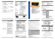
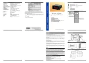
4.Front Panel Definition and Accessing to the Menus
BUTTON DEFINITIONS1.
1. Increment Button :
** It is used to increase the value in the Programming mode.
2. Decrement Button :
** It is used to decrease the value in the Programming mode.
** To access the programming screen; in the main operation screen, press this button for 5
seconds.
LED DEFINITIONS
5. Alarm Output Led :
** The led is active when the measurement method AC is selected.
** Blinks in programming mode .
5 6 9 10
121187
1-Before mounting the device in your panel,
make sure that the cut-out is of the right size.
2-Insert the device through the cut-out. If the
mounting clamps are on the unit, put out them
before inserting the unit to the panel.
3- Insert the mounting clamps to the fixing sockets
that located left and right sides of device and make
the unit completely immobile within the panel
Before starting to remove the unit from
panel, power off the unit and the related
system.
2.3 Panel Mounting
2.4 Removing from the Panel
3. PROKEY ANAHTARININ KULLANIMI
3
2
1
5 6 7 8
1
2
3
4
P
EDA-3700
3
1
3
2
1-Pull mounting clamps from left and right fixing
sockets.
2-Pull the unit through the front side of the panel
** The led is active when the alarm relay is active.
3.1 Supply Voltage Input Connection of the Device
Power Supply Connection
EXTERNAL
Note-1
Supply
Switch
SupplyVoltage
4 5
L N
230V ( %15) 50/60Hz ,
115V ( %15) 50/60Hz,
24V ( %15) 50/60Hz,
±
±
±
10...30 V - 1.5 W
Must be determined in order.
Make sure that the power supply voltage is the same
indicated on the instrument.
Switch on the power supply only after that all the
electrical connections have been completed.
Supply voltage range must be determined in order.
While installing the unit, supply voltage range must be
controlledand appropriate supply voltage must be
applied to the unit.
There is no power supply switch on the device. So a power
supply switch must be added to the supply voltage input.
Power switch must be two poled for seperating phase and
neutral, On/Off condition of power supply switch is very
important in electrical connection.
3.2 Device Label and Connection Diagram
230VVCONNECTION
P/N:EDA-3700.5.09.1.1/00.00/0.0.0.0
230 V ± 15%
50/60Hz - 1.5VA
7 8
9 10 11 12
+
Max.
/ /
Max. 60mV
/ /
+
- -
5A
OUTPUT
8A@250V
BACOM.
230 V ± 15%
50/60Hz - 1.5VA
7 8
9 10 11 12
+
Max.
/ /
Max. 60mV
/ /
+
- -
5A
OUTPUT
8A@250V
BACOM.
AC
DC
AC
DC
EDA-37 00
AC
DC
EDA-37 00
EDA-37 00
P
AC
DC
3. Program Button:
4. Enter Button:
It is used to saving value in the programming screen.
6. AC Measurement Led :
7. DC Measurement Led:
** The led is active when the measurement method DC is selected.
8. Program led:
** If AC / DC is selected, AC and DC will be active at the same time.
3. Electrical Wiring Diagram
21 5 7 8
P/N : EDA-3700
3
Relay
L
N
Supply Voltage Input
230V ( %15) 50/60Hz±V
115V ( %15) 50/60Hz±V
24V ( %15) 50/60Hz±V
24V ( %15) 50/60Hz±W
1094 6 1112
Ak mı
AC
DC
AC/DC
+
-
+
-
mV
AC
DC
AC/DC
COM.
A
B
5. Programming Mode Parameter List
Measurement Metod Parameter( Default = AC/dC)
Current conversion ratio parameter (Default = 5)
It can be set from 5 to 9999. If this parameter is changed, these parameters
Can be set to AC, DC, AC/DC.
Measurement method is AC.
Measurement method is DC.
Measurement method is AC/DC.
Sampling Time Parameter ( Default = 4)
Sampling time : 250ms
Sampling time : 500ms
Sampling time : 750ms
Sampling time: 1sn
Sampling time is set with this parameter. It can be adjusted from 0 to 3.
Up Limit Alarm Set Parameter( Default = 5.000)
Up Limit Alarm Hysteresis Parameter ( Default = 0.100)
/ 5
Up Limit Alarm On Delay Time Parameter ( Default = 0)
It can be adjusted from 0 to 999.
Low Limit Alarm Set Parameter( Default = 0.000)
It can be adjusted between lower scale and upper scale that is specified with
parameter. This parameter can't be higher than
Low Limit Alarm Hysteresis Parameter( Default = 0.100)
Low Limit Alarm On Delay Time Parameter ( Default = 0)
Decimal Point Position Parameter ( Default = 0.000 )
Decimal Point Position is determined by this parameter. It can be adjusted from 0 to 3.
Up Limit Alarm Delay Parameter After Power On
It can set from 0 to 999 seconds.
Device communication address parameter (1 to 247).
Programming SectionAccessing Password ( Default = 0 )
It is used for accessing to the programming section. It can be adjusted from 0 to 9999.
If it is selected 0, password will not be asked.
A
-A
0T/2 T 3T/2 2T
DCAC
AC/DC(rms)
3
1
A3
1
A 0.000
A
-A
0T/2 T3T/2 2T
A A 0.000
A
0T/2 T 3T/2 2T
2
1
A2
1
A2
1
A
A
0d d
T 2T
T
d
AAT
d
T
d
-
2
2
T
d
A
0
A
-A
T/2 T 3T/2 2T
2
1
A2
1
A0.000
0
A
T/2 T 3T/2 2T
2
1
A
π
2
A0.308A
0
A
T/2 T 3T/2
2
1
A 0.386A
π
1
A
5.1 Operations Graphics of EDA-3700 AC/DC Ammetre 5.2 EDA-3700 AC/dC Ampermetre Cihaz Alarm Çal ma Grafikleriı ış
Input
cUH
cUH - HSU
cUL + HSL
cUL
dLU dLL dLLdLU
Low Limit Alarm On Delay Time Parameter 1
Alarm Set Value Low Limit Parameter
Alarm Set Value Up Limit Parameter
Press enter button for saving the
parameter.
Press increment button for accessing to the
next parameter, press decrement button for
accessing to the previous parameter
When PROG button is pressed for 5
seconds, “P” led starts to blink. If
programming mode entering
password is different from 0,
programming mode entering screen
will be observed.
Main Operation Screen
Programming Screen
Change the value with increment
and decrement buttons.
Current Conversion Ratio
Parameter Value
Press enter button for accessing to the parameter
value. Press increment button for accessing to the
next parameter, press decrement button for
accessing to the previous parameter.
Press ENTER button for
accessing to the
password entering
screen.
Enter programming mode accessing password
with increment and decrement buttons.
Note-2:If programming mode accessing password is 0,only three parameters
area ccessible,and the parameter values can be changed.
Press ENTER button for
entering the password.
Current Conversion Ratio
Parameter Value
If no operation is performed in programming mode for 20 seconds, device turns to main
ioperation screen automatically..
i
Measurement Method Parameter
5. 3 Entering to the Programming Mode, Changing and Saving Parameters
OF PS
EDA-3700
SP
EDA-3700
F S P
EDA-3700
OF S P
EDA-3700
OFSP
EDA-3700
O
FSP
EDA-3700
O
F S P
EDA-3700
F S P
EDA-3700
Password Entering Screen
Note1: If programming
mode accessing password
is 0, Current conversion
ratio parameter is
observed instead of
programming screen
P
P
P
P P
P
P
P
6. Monitoring of Software Revision of EDA-3700 Devices
OF PS
EDA-3700
P
AC
DC
6.1 Error Messages on EDA-3700 AC / DC Ammeter
O
F PS
EDA-3700
P
AC
DC
O
F PS
EDA-3700
P
AC
DC
When the measured current value exceeds the upper scale,
"nnnn" and "9999" are alternately displayed on the screen.
When the measured current value exceeds the subscale,
"uuuu" and "-1999" are alternately displayed on the screen.
When the AC / DC ammeter is energized, firstly the revision number of the software is displayed to
the user.
Software revision number
'' rU " Revision letter
, , , ) must be updated again.
NC
NO
C
InputInput
Must be determined in order.
Output
DIAGRAM
External fuse that on power supply inputs must be on
phase connection.
External fuse that on power supply inputs must be on
(+) connection.
External fuse is recommended.Note-1:
FUSE
1A T
(Slave ID Parameter
It can set from 0 to 999 seconds.
No point “0”
Between first and second digits “0.0”
Between first and second digits “0.00”
Between first and second digits “0.000”
This parameter can not be greater than
It can be adjusted from 0 to .
/ 5
This parameter can not be greater than
It can be adjusted from 0 to .
Password Entering Screen
It can be adjusted between minimum and maximum scale that is specified with
parameter. This parameter can't be lower than
(This output is available on alarm
output devices)
V
Z
W
V
Z
W
V
V
V
V