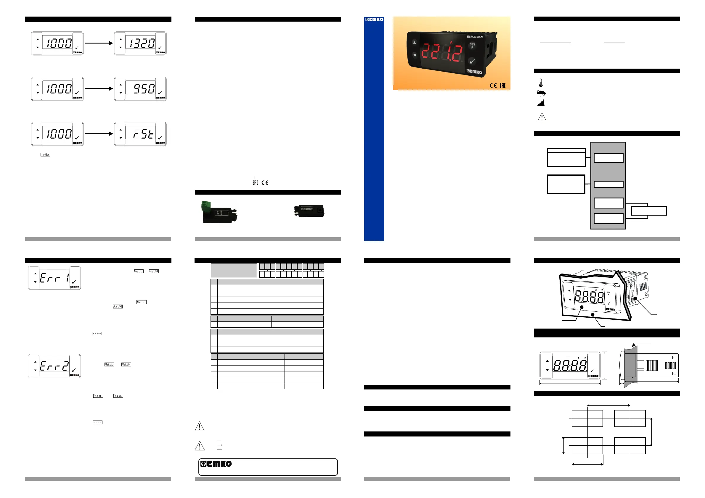
2.2 Panel Cut-Out
If the equivalent voltage or current applied to
the process input while in or
parameter for user reading adjustment is
out of the standard scale, this error message
are shown on the display.
Example-1:
For process Input type selected as 0-10 V , If
the applied voltage while in
parameter or parameter is lower than
0 V or upper than 10 V , when the
decrement or increment button is pressed for
saving the analog value this errror message is
shown on the display and applied voltage value
is not saved.
Press any button to clear error
message from the display and turn to the user
reading adjustment analaog value entering
screen
If the difference between the equivalent
voltage or current applied to the process input
while in and parameters
for user reading adjustment is lower than the
%50 of the standard scale, this error message
are shown on the display
Example-2:
For process Input type selected as 0-10 V , If
the difference between the applied voltages in
and parameters is
lower than the 5 V , when the decrement or
increment button is pressed for saving the
analog value this errror message is shown on
the display and applied voltage value is not
saved.
Press any button to clear error
message from the display and turn to the user
reading adjustment analaog value entering
screen
2. General Description
2.1
ESM-3700-N 77x35 DIN Size
Digital Process Indicator
Instruction Manuel. ENG ESM-3700-N 01 V00 05/18
- 4 Digits Display
- Easily adjustable from front panel
- Between -1999 and 9999 display adjustment scale
- Adjustable decimal point
- Selectable universal process Input
- Adjustable input filter
- Minimum and maximum measured values in the memory storage
- Maximum or minimum measurement value can be shown
- User can be adjust device’s reading value for selected input type
- Alarm output
- Adjustable alarm set value from front panel
ESM- 77 x 35 DIN Size3700-N
Digital Process Indicator
Operating Temperature :
0 ile 50 °C
Max. Operating Humidity : 90% Rh (non-condensing)
:Altitude Up to 2000 m
1.2 General Specifications
1.Preface
Applications
Glass
Flood
Plastic
Petro-Chemistry
Textile
Machine Production Industries...
2
1.1 Environmental Ratings
3 41615
13 14
ESM-3700-N
Alarm Output
230V ( %15) 50/60Hz
Optional Supply Voltage
115 V( %15) 50/60Hz,
24 V( %15) 50/60Hz,
24 V(-%15,+%10)50/60Hz
±
±
Standard
Optional
Alarm Output
(Relay Output)
110 mm / 4.33 inch (min)
50 mm / 1.97 inch (min)
29 mm / 1.14 inch
71 mm / 2.79 inch
1.3 Installation
1.4 Warranty
1.5 Maintenance
1.6 Manufacturer Company
Maximum 15 mm / 0.59 inch
Front Panel
IP65 protection
76 mm / 3 inch
6 mm / 0.24 inch
34,5 mm / 1.36 inch
65 mm / 2.56 inch
ESM3700-N
SET
P
±
ESM3700-N
(0-10V , 0-1V, 0-60mV, 0-20mA , 4-20mA )
- Programming mode password protection
Relay or SSR driver output (It must be determined in order.)
(0-10 V)
(0-1 V)
(0-60 mV)
(0-20 mA)
(4-20 mA)
12.Ordering Information
A BC D E FG HI /
/
U
V W Z/
/
0 00 0 0 000 0
Alarm Output
E
Supply Voltage
A
24 V ( ± 15% ) 50/60 Hz
3
115 V ( ± 15% ) 50/60 Hz
4
230 V ( ± 15% ) 50/60 Hz
5
2
SSR Driver Output (Maximum 28 mA,15 V )
1
Relay Output (Resistive load 5 A@250 V ),1NO + 1NC
Customer
9
0
None
2
24 V ( -%15, +%10 ) 50/60 Hz
ESM-3700-N
(77 x 35 DIN Size)
Your Technology Partner
www.emkoelektronik.com.tr
Alarm Output
BC
20
Configurable(Table-1)
Scale
Table-1
Input Type ( Voltage/Current)
47
BC
46
44
43
45
Scale
-1999, 9999
-1999, 9999
-1999, 9999
-1999, 9999
-1999, 9999
Input empedance (current) is 5 . So do not applied voltage to the current input
Ω
Vac
Thank you very much for your preference to use Emko Elektronik
products, please visit our web page to download detailed user
manual.
Vac/dc
Device Type
Housing & Mounting
Protection Class
Weight
Enviromental Ratings
Storage / Operating Temperature
Storage / Operating Humidity
Installation
Overvoltage Category
Pollution Degree
Operating Conditions
Process Input
Accuracy
Supply Voltage and Power
Alarm Relay Output
Optional SSR Output
Display
LEDs
: Digital Process Indicator
: 77mm x 35mm x 62.5mm Plastic housing for panel
mounting. Panel cut-out is 71x29 mm.
: IP65 at front, IP20 at rear.
: Approximately 0.16 Kg.
: Standard, indoor at an altitude of less than 2000 meters
with none condensing humidity.
: Fixed installation
: II.
: II, office and workplace, none conductive pollution
: Continuous.
: ± 5 % of full scale
115 V
Electrical Life: 100 000 operation (full load)
: 10 mm Red 4 digits LED Display
A(Green), P(Green)
: Approvals
9. Specifications
: -40 C to +85 C / 0 C to +50 C
: 90 % max. (none condensing)
o
o
o
o
: Maximum 28 mA, Maximum15 V
: 230 V
24 V
V (-%15, +%10) 50/60 Hz. 1.5 24 VA
50/60 Hz. 1.5 VA(-%15;+%15)
50/60 Hz. 1.5 VA(-%15;+%15)
50/60 Hz. 1.5 VA(-%15;+%15)
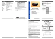
RS-485 Communication Interface
1.RS-485 Module
2.PROKEY Programming Module
It is used to upload and download
: 5 A@250 V
(Red),
: 0..10 V Input Empedance Approximately 11k
Ω
Measurement range 0...12 V
0..1 V Input Empedance Approximately 11k
Ω
Measurement range 0...1.2 V
0..60mV Input Empedance Approximately 11k
Ω
Measurement range 0...100 mV
0..20mA Input Empedance Approximately 5
Ω
Measurement range 0...22 mA
4..20mA Input Empedance Approximately 5
Ω
Measurement range 0...22 mA
Sampling Time
: 240ms for 0-20mA and 4..20mA process input
150ms for 0-60mV process input
100ms for 0-1 V and 0..10Vprocess input
12V Voltage Output : 12 V ( 35%Max.30 mA)
10. Optional Accessories
8. ESM-3700-N Front Panel Functions
ESM3700-N
SET
P
ESM3700-N
SET
P
ESM3700-N
SET
P
ESM3700-N
SET
P
ESM3700-N
SET
P
ESM3700-N
SET
P
O
F
PS
SET
P
O
F
PS
SET
P
11. Failure Messages in ESM-3700-N Digital Process Indicator
ESM3700-N
ESM3700-N
continuously on the display
A visual inspection of this product for possible damage occurred during shipment is
recommended before installation. It is your responsibility to ensure that qualified mechanical
and electrical technicians install this product.
If there is danger of serious accident resulting from a failure or defect in this unit, power off
the system and separate the electrical connection of the device from the system.
The unit is normally supplied without a power supply switch or a fuse. Use power switch and
fuse as required.
Be sure to use the rated power supply voltage to protect the unit against damage and to prevent
failure.
Keep the power off until all of the wiring is completed so that electric shock and trouble with the
unit can be prevented.
Never attempt to disassemble, modify or repair this unit. Tampering with the unit may results in
malfunction, electric shock or fire.
Do not use the unit in combustible or explosive gaseous atmospheres.
During putting equipment in hole on the metal panel while mechanical installation some metal
burrs can cause injury on hands, you must be careful.
Montage of the product on a system must be done with it’s fixing clamps. Do not do
the montage of the device with inappropriate fixing clamp. Be sure that device will not fall while
doing the montage.
It is your responsibility if this equipment is used in a manner not specified in this instruction
manual.
EMKO Elektronik warrants that the equipment delivered is free from defects in material and
workmanship. This warranty is provided for a period of two years. The warranty period starts
from the delivery date. This warranty is in force if duty and responsibilities which are determined
in warranty document and instruction manual performs by the customer completely.
Repairs should only be performed by trained and specialized personnel. Cut power to the
device before accessing internal parts.
Do not clean the case with hydrocarbon-based solvents (Petrol, Trichlorethylene etc.). Use of
these solvents can reduce the mechanical reliability of the device. Use a cloth dampened in
ethyl alcohol or water to clean the external plastic case.
Manufacturer Information:
Emko Elektronik Sanayi ve Ticaret A.Ş.
Demirtaş Organize Sanayi Bölgesi Karanfil Sk. No:6 16369 BURSA/TURKEY
Phone : +90 224 261 1900
Fax : +90 224 261 1912
Repair and maintenance service information:
Emko Elektronik Sanayi ve Ticaret A.Ş.
Demirtaş Organize Sanayi Bölgesi Karanfil Sk. No:6 16369 BURSA /TURKEY
Phone : +90 224 261 1900
Fax : +90 224 261 1912
ESM-3700 series Digital Process Indicators are design for measuring the process value.
They can be used in many applications with their easy use, alarm output, universal process input
properties.
Some application fields which they are used are below:
Application Fields
Transmitter application of temperature,
Speed measurement of motor driver
Current measurement over the shunt
resistance,
Food Pressure,humidity etc.
Etc...
Forbidden Conditions:
Corrosive atmosphere
Explosive atmosphere
Homeapplications (The unit is only for industrial applications)
Power Supply
Input
Process Input
Optional
Alarm Output
(SSR Driver Output)
Panel surface
Mounting Clamp
Front View and Dimensions of ESM-3700 Digital Process Indicator
at resistive load
:
parameters to the device.
0..60mV
0..1 V
0..10 V
0..20mA
4..20mA
2.2 Panel Cut-Out
All order information of ESM-3700-N Digital Process Indicator are given on the table at left.
User may form appropriate device configuration from information and codes that at the table
and convert it to the ordering codes. Firstly, supply voltage then other specifications must
be determined. Please fill the order code blanks according to your needs.
Please contact us, if your needs are out of the standards.
Vdc
while the device is in current measurement mode.
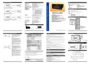
Main Operation Screen
If push the up button, in main operation screen
show the maximum measurement process
value.
If push the down button, in main operation screen
show the minimum measurement process
value.
If push together up and down button, in main operation screen
show message and minimum and maximum measurement
process values are reset.