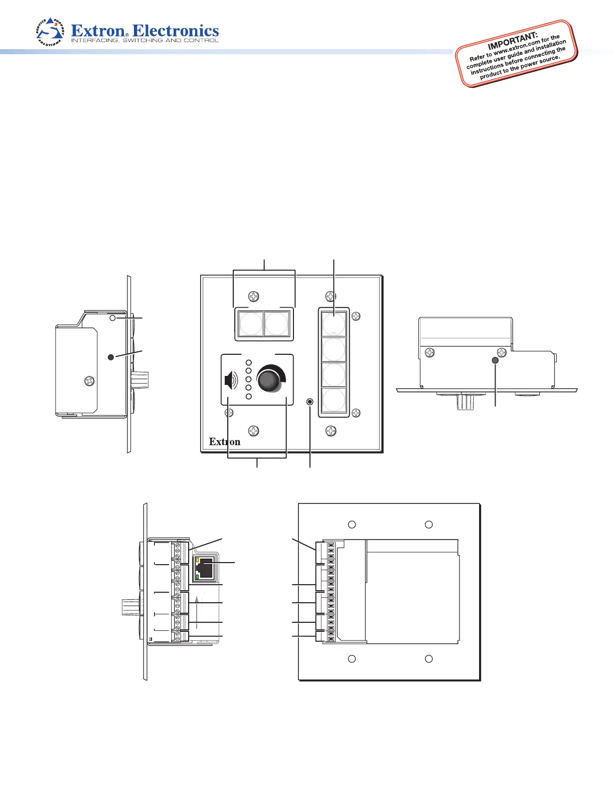
Extron MLC 104 IP Plus AAP Manual
Læs gratis den danske manual til Extron MLC 104 IP Plus AAP (6 sider) i kategorien Fjernbetjening. Denne vejledning er vurderet som hjælpsom af 35 personer og har en gennemsnitlig bedømmelse på 4.0 stjerner ud af 18 anmeldelser.
Har du et spørgsmål om Extron MLC 104 IP Plus AAP, eller vil du spørge andre brugere om produktet?
Produkt Specifikationer
| Mærke: | Extron |
| Kategori: | Fjernbetjening |
| Model: | MLC 104 IP Plus AAP |
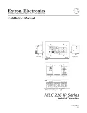
| Bredde: | 209 mm |
| Dybde: | 3 mm |
| Højde: | 114 mm |
| Vægt: | 300 g |
| Produktfarve: | Sort |
| Indbygget skærm: | Ingen |
| Grænseflade: | Ledningsført |
| Indbygget batteri: | Ingen |
| Mærke kompatibilitet: | Extron |
| Fjernbetjening korrekt brug: | AV-kontakt |
| Indgangstype: | Trykknapper/hjul |
| Maks. rækkevidde: | - m |
| Antal understøttede enheder: | 1 |
| Genopladelig: | Ingen |
Har du brug for hjælp?
Hvis du har brug for hjælp til Extron MLC 104 IP Plus AAP stil et spørgsmål nedenfor, og andre brugere vil svare dig
Fjernbetjening Extron Manualer

Fjernbetjening Manualer
- Rii
- Hamilton Buhl
- Niko
- EZVIZ
- Infinity
- Delta Dore
- Geemarc
- Steren
- Gefen
- Brandson
- Phoenix Technologies
- Ikea
- Plugwise
- GoPro
- VIZIO
Nyeste Fjernbetjening Manualer