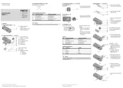
Festo CPX-FB14 Manual


Læs gratis den danske manual til Festo CPX-FB14 (3 sider) i kategorien Ikke kategoriseret. Denne vejledning er vurderet som hjælpsom af 18 personer og har en gennemsnitlig bedømmelse på 4.8 stjerner ud af 9.5 anmeldelser. Har du et spørgsmål om Festo CPX-FB14, eller vil du spørge andre brugere om produktet?

Side 1/3
CPX bus node CANopen
CPX-FB14
Festo SE & Co. KG
Ruiter Straße 82
73734 Esslingen
Germany
+49 711 347-0
www.festo.com
Brief description
Translation of the original instructions
8101627
2018-11c
[8101629]
CPX bus node CANopen CPX-FB14 English. . . . . . . . . . . . . . . . . . . . . . . . . . . . . . . .
For all available product documentation è www.festo.com/pk
1 User instructions
The bus node CPX-FB14 for CPX terminals is intended exclusively for use as a parti
cipant (Slave) in a CANopen network.
The specified limits for technical data must be adhered to. You can find detailed
information in the bus node description P.BE-CPX-FB14-... and in the CPX system
description P.BE-CPX-SYS-.…
CANopen® and TORX® are registered trademarks of the respective trademark
owners in certain countries.
Warning
Switch off the power supply before assembling or disassembling modules or
plugging plug connectors together or separating them (danger of operative
malfunctions or damage).
Only use PELV circuits in accordance with IEC/EN 60204-1 (protective extra-
low voltage, PELV) for the electrical power supply.
Observe also the general requirements for PELV power circuits in accordance
with IEC/EN 60204-1.
Only use voltage sources which guarantee reliable electrical isolation of the
operating voltage in accordance with IEC/EN 60204-1.
Connect an earth conductor of sufficient cable cross section to the connection
of the CPX terminal marked with the earth symbol.
Note
The CPX bus node contains electrostatically sensitive devices.
Therefore, do not touch any components.
Observe the handling specifications for electrostatically sensitive devices.
This will help to prevent damage to the electronics
Note
Only commission a CPX terminal which has been completely mounted and
connected.
2 Connection and display components
MS PS
PL
SF
M
NS
IO
51
96
1
2
4
3
1Bus-status-specific and
CPX-specific LEDs
2Fieldbus connection (9-pin Sub-D
plug)
3Cover for DIL switches
4Service interface for handheld,
etc.
Fig. 1
CANopen-specific LEDs CPX-specific LEDs
MS Module status (green/red) 1) PS Power system (green) 1)
NS Network status (green/red) 1) PL Power load (green) 1)
IO I/O status (green/red) 1) SF System failure (red) 1)
M Modify (yellow) 1) 2)
1) P.BE-CPX-FB14-Detailed information: è bus node description
2) Parameterisation revised or “Force” active
Fig. 2
Normal operating status:
The LEDs MS, NS, IO, PS and PL light up green; the LEDs SF and M do not light up.
3 Installation instructions
3.1 Mounting/dismounting
When built-in, the bus node is located in an interlinking block of the CPX terminal.
3
1
2
4
1TORX T10 screws; tightening
torque 0.9…1.1 Nm
2Bus node CPX-FB14
3Contact rails
4Interlinking block
Fig. 3
Warning
Switch off the power supply before assembling or disassembling bus nodes
(danger of operative malfunction or damage).
Dismantling:
Unscrew screws and carefully lift off the bus node.
Mounting:
1. Check seal and seal surfaces.
2. Carefully insert connection block into the interlinking block and press it in.
3. Screws must be set so that the existing self-cutting threads can be used.
Tighten the screws by hand in diagonally opposite sequence. Tightening
torque: 0.9 … 1.1 Nm
Note
Always use the appropriate screws for the interlocking block, which depend on
the material of the interlinking block (metal or plastic):
Plastic interlinking block: thread-cutting tapping screws
Metal interlinking block: screws with metric thread
3.2 Setting the DIL switches
1 2 3 4 5 6 7 8
1 2 1 2
On On
1 2 1 2
On On
On
1
2
3
4
5
1DIL switch 1: bus node operating mode
2DIL switch 2: undervoltage error message mode
3DIL switch 3 station number/LSS activation
4DIL switch 4 baud rate
5DIL switch 5 CPX diagnostics mode or number of log. I/Os with “remote
controller
Fig. 4
Setting the operating mode with DIL switch 1
You can set the operating mode of the bus node with switch element 1.1 of the
dual DIL switch 1:
DIL switch 1Function
DIL 1.1: OFF
DIL 1.2: OFF
(factory setting)
Remote I/O operating mode
All functions of the CPX terminal are controlled
directly by the CANopen Master.
DIL 1.1: ON
DIL 1.2: OFF
Remote Controller
A CPX-FEC or CPX-CEC integrated into the terminal
controls all functions
Fig. 5
Setting the fault mode with DIL switch 2
Set the fault mode with the dual DIL switch:
DIL switch 2Function
DIL 2.1: OFF
DIL 2.2: OFF1)
(factory setting)
Registering undervoltage error
DIL 2.1: ON
DIL 2.2: OFF1)
Filtering undervoltage error
Faults during the monitoring of the operating and load
voltage supplies will be ignored
1) The setting of the switch element DIL 2.2 is reserved (always OFF).
Fig. 6
Setting the station number with DIL switch 3
Set the station number using the switch elements 1 ... 7 of the 8-element DIL
switch:
DIL switch 3Function
1 2 3 4 5 6 7 8
20
21
22
23
24
25
26
DIL 3.8 Resetting the bus node to factory setting
( Fig. 9).è
DIL 3.1 … DIL3.7 Binary-coded input of the station number.
Example on left in diagram:
21 + 22 + 25 =
2 + 4 + 32 = station number 38
Permissible station numbers: 1 127
Fig. 7
Activation of the layer setting service with DIL switch 3
The bus node CPX-FB14 supports layer setting service (LSS) in accordance with
CiA DSP-305.
To activate LSS, set the switch elements 1 … 7 of the DIL switch to OFF (station
number = 0):
DIL switch 3Function
1 2 3 4 5 6 7 8
20
21
22
23
24
25
26
DIL 3.8 Resetting the bus node to factory setting
( Fig. 9).è
DIL 3.1 … DIL 3.7 Binary-coded input of the station number.
Example in the left figure:
Station number = 0, LSS is activated
Fig. 8
Resetting the bus node to factory setting with DIL switch 3
Reset the bus node to factory setting with switch element 8 of the DIL switch:
DIL switch 3Function
1 2 3 4 5 6 7 8
20
21
22
23
24
25
26
DIL 3.8 Resetting the bus node to factory setting:
1. Switch off the power supply for the CPX
terminal.
2. Set the DIL switch 8 to ON.
3. Switch on the power supply for the CPX
terminal.
The bus node is reset to factory settings.
4. Set the DIL switch 8 back to OFF.
DIL 3.1 … DIL3.7 Binary-coded input of the station number
( Fig. 7)è
Fig. 9
Setting the baud rate with DIL switch 4
Set the baud rate with the dual DIL switch:
DIL switch 4
125 kbaud 250 kbaud 500 kbaud 1000 kbaud
DIL 4.1: OFF
DIL 4.2: OFF
DIL 4.1: ON
DIL 4.2: OFF
DIL 4.1: OFF
DIL 4.2: ON
DIL 4.1: ON
DIL 4.2: ON
2)
Fig. 10


Produkt Specifikationer

Mærke: Festo
Kategori: Ikke kategoriseret
Model: CPX-FB14

Har du brug for hjælp?

Hvis du har brug for hjælp til Festo CPX-FB14 stil et spørgsmål nedenfor, og andre brugere vil svare dig


Ikke kategoriseret Festo Manualer

Ikke kategoriseret Manualer

Nyeste Ikke kategoriseret Manualer

Kimo

Kimo LR 110 Manual

2 September 2025
HMS Premium

HMS Premium LPD02 Manual

2 September 2025
AVer

AVer E1008 Manual

2 September 2025
Biltema

Biltema 17-547 Manual

2 September 2025
Groen

Groen AH/1E Manual

2 September 2025
ACOPower

ACOPower HY-P30 Manual

2 September 2025
Globe

Globe RG30 Manual

2 September 2025
Neutrik

Neutrik NLT4FXX Manual

2 September 2025