Festo DGC-8 Manual
Festo
Ikke kategoriseret
DGC-8
Læs nedenfor 📖 manual på dansk for Festo DGC-8 (4 sider) i kategorien Ikke kategoriseret. Denne guide var nyttig for 15 personer og blev bedømt med 5.0 stjerner i gennemsnit af 8 brugere
Side 1/4

DGC-8 ... 63-...
Festo SE & Co. KG
Ruiter Straße 82
73734 Esslingen
Germany
+49 711 347-0
www.festo.com
Operating instructions
Original instructions
8075213
2017-07h
[8075215]
Linear drive DGC-8 ... 63-... English. . . . . . . . . . . . . . . . . . . . . . . . . . . . . . . . . . . . . .
For all available product documentation è www.festo.com/pk
Note
Fitting and commissioning is to be carried out only by qualified personnel in
accordance with the operating instructions.
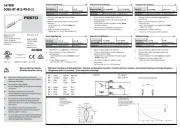
1 Operating elements and connections
1 2 3 4
7
5 6
9
7 8
1Thread for mounting the cylinder
foot1) or for direct mounting
2Shock absorber or elastomer
shock absorber (exchangeable
è chapter “Commissioning”)
3Guide rail
4Slide
5Centring hole for effective load
6Fastening thread for work load
7Compressed air connections
8Groove for proximity sensor
1)
9Adjusting screw for end position
cushioning
1) Accessories
Fig. 1
2 Function and application
When the compressed air is ports are pressurized
alternately, the piston moves backwards and forwards
in the tubing. By means of a rigid connection, the
outer slide also moves. The slot in the cylinder barrel
required for this is covered by a band system.
Fig. 2 Circuit symbol
The DGC is intended for the space-saving transport of
masses.
Both the slide mode and the yoke operating modes
are permitted (observe loading limits).
Unpressurised movement of the slide is permitted
only for fault elimination and at low speed. If the
speed is too high, the resulting partial vacuum can
pull the sealing band into the piston chamber. This
leads to:
– severe leakage and
– impermissible accelerations (e.g. with a vertical
mounting position).
Fig. 3 Slide operation
Fig. 4 Yoke operation
3 Transport and storage
Note
Avoid touching the guide rail with your hands during transport und storage.
Otherwise the layer of grease will be damaged.
Consider the weight of the DGC.
Depending on the design, the DGC weighs over 150 kg.
For transport, the transport belts must be spaced according to the permissible
support distances (support distances è Fig. 6).
4 Requirements for product use
Note
Malfunctions will occur if the device is not used correctly.
Be sure to always comply with the specifications in this chapter.
Note the warnings and instructions on the product and in the relevant operat
ing instructions.
Compare the maximum values specified in these operating instructions with
your actual application (e.g. forces, torques, temperatures, masses).
Only observance of the load limits allows operation of the product in compliance
with the relevant safety regulations.
Take into consideration the ambient conditions at the location of use.
Corrosive elements in the environment (e.g. ozone) will reduce the service life of
the product.
Please comply with national and local safety laws and regulations.
Use the product in its original state without any unauthorised modifications.
Remove packaging, such as foils and cardboard.
Exception:
– The plastic cover on the aluminium guide rail (with DGC-…-G/GF).
The packing is intended for recycling (except for: oiled paper = general waste).
Make sure that the compressed air is properly prepared è 11 Technical Data
Take the tolerance of the tightening torques into account. Unless otherwise
specified, the tolerance is ±20%.
5 Installation
5.1 Fitting mechanical components
Avoid pushing in or sucking in the sealing band.
Damage to the sealing band reduces its reliability in operation. Jerky movement
of the unpressurised slide can cause a partial vacuum that sucks the sealing
band into the piston chamber.
Leave all screws and threaded bolts in their original states, unless you are
requested to modify them in these instructions.
Do not allow the band system to become damaged or excessively dirty.
Damage to the DGC will reduce its reliability and service life.
Make sure that the device is fitted free of mechanical stress and distortion.
Use the foot mounting adapter HPC to mount the DGC on the end caps.
Turn the mounting screws until they are equally tight.
Tightening torques [Nm]
HPC-8 HPC-12/18 HPC-25 HPC-32/40 HPC-50 HPC-63
0.8 1.6 2 4.5 15 23
Fig. 5
Drives with long stroke lengths:
Use the support spacings (l) for the profile attachments MUC è Fig. 6.
8
12
18
25
32
40
50
63
F
l l

lF
l
8
12
18
25
32
40
50
63
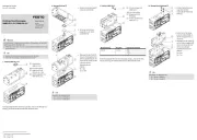
Fig. 6 This shows the support spacings required for the various fittings
Fitting profile fastenings type MUC:
1. Place the profile fastenings equally over the entire length of the drive, and not
just over the stroke length.
2. Fasten the profile fastenings on the DGC è Fig. 7.
Fig. 7
3. Turn the clamping screws until they are equally tight.
Tightening torques [Nm]
MUC-8/12 MUC-18 MUC-25/32 MUC-40 MUC-50/63
1.2 4.1 8.3 14 20
Fig. 8
4. Make sure that the profile attachment does not
collide with the slide or effective load (especially
with lateral mounting). To do this, push the slide
with the effective load over the complete travel
distance.
Fig. 9
With hard and stiff effective loads:
Fig. 10
Note
If the slide becomes bent because of a
buckled effective load, the service life
of the guide will be reduced.
Make sure that the mounting sur
face of the effective load has the
following flatness (t):
– G/GF: t 0.03 mm
– KF/FA: t 0.01 mm
Note the tightening torques when fastening the work load on the slide:
Tightening torques [Nm]
DGC- 8/12 18 25/32 40 50/63
M4 2 – – – –G
KF 2.5
M5 – 3.5 3.5 3.5 –
M6 – 6.5 6.5 6.5
M8 – – 10
Fig. 11
Effective loads with own guide:
Adjust the guides of the work load and of the DGC so that they are exactly
parallel.
This is the only way to avoid overloading the slide è 11 Technical Data: Perm.
forces.
5.2 Fitting pneumatic components
Installation in a vertical or diagonal position:
Warning
If there is a power failure, the work mass will slide down. Danger of crushing!
Check whether non-return valves HGL are necessary.
In this way, you can prevent the work mass from sliding down suddenly.
Check whether safety measures are necessary to prevent the mass from sink
ing down slowly as a result of leakage (e.g. toothed latches or moveable
bolts).
Select the supply ports.
In addition to the supply ports
provided at the factory (W), there are
also the alternative ports (A). These
are fitted with plug screws.
W = Supply ports ex works
A = Alternative ports
Fig. 12
W
W
A
AA
Aø 8/12
l
r
LR
With sizes 18 … 63 the compressed
air can be connected on one side
(right).
L = end position left
R = end position right
l = movement to the left
r = movement to the right
Fig. 13
ø 18 ... 63
W (r)
A (l)
AA
W (l)
LR
l
rA (r)
Setting the slide speed:
Rotate the one-way flow control valves GRLA into the supply ports.
5.3 Installing the electric components
Position scanning with proximity sensors SME/SMT:
Use grooves (S) from Fig. 16 to mount the proximity sensors.
Observe the minimum distances between ferritic masses and the proximity
sensors.
In this way you will avoid incorrect switching as a result of external influences.
Minimum clearances [mm]
POS 8 12 18 25 32 … 63
L1 10 0 0
12
2– 0 0
L2 120 10 10 0
2– 25 25
L3 130 25 25 25
2– 10 25 0
L4 10 0 0
2– 0 0
Fig. 14 (POS = position of proximity sensor)
Place the proximity sensor on DGC-8/12 as follows:
Position SME-10/SMT-10F-KL (-SL) SME-10/SMT-10F-KQ (-SQ)
End position left
(“L” è Fig. 12)
Cable exit to cylinder centre neces
sary
Fastening screw faces end cap
End position right
(“R” è Fig. 12)
Fitting position, any Fitting position, any
Fig. 15
In this way, you take into consideration the fact that the switching solenoid is
arranged asymmetrically (left) on the internal slide.
In case of continuous signal:
Check whether the proximity switch has been fitted the right way round.
Laying the cables for the proximity switches:
Note that the cables for the proximity switches can be passed through the
groove.
Produkt Specifikationer
Mærke: | Festo |
Kategori: | Ikke kategoriseret |
Model: | DGC-8 |
Har du brug for hjælp?
Hvis du har brug for hjælp til Festo DGC-8 stil et spørgsmål nedenfor, og andre brugere vil svare dig
Ikke kategoriseret Festo Manualer

10 Januar 2025

10 Januar 2025

7 Januar 2025

7 Januar 2025

6 Januar 2025

6 Januar 2025

6 Januar 2025

21 December 2024

21 December 2024

17 November 2024
Ikke kategoriseret Manualer
- Ikke kategoriseret Brüder Mannesmann
- Ikke kategoriseret BendixKing
- Ikke kategoriseret ALC
- Ikke kategoriseret Elite Force
- Ikke kategoriseret Primewire
- Ikke kategoriseret UNYKAch
- Ikke kategoriseret Victrola
- Ikke kategoriseret AmerBox
- Ikke kategoriseret Qu-Bit
- Ikke kategoriseret Adviti
- Ikke kategoriseret Momini
- Ikke kategoriseret AstralPool
- Ikke kategoriseret Eltako
- Ikke kategoriseret Galanz
- Ikke kategoriseret Prowise
Nyeste Ikke kategoriseret Manualer

29 Maj 2025

29 Maj 2025

10 April 2025

10 April 2025

10 April 2025

10 April 2025

10 April 2025

10 April 2025

10 April 2025

9 April 2025