Festo EAMM-A-D32-35A-40A Manual

Festo Ikke kategoriseret EAMM-A-D32-35A-40A

Læs gratis den danske manual til Festo EAMM-A-D32-35A-40A (4 sider) i kategorien Ikke kategoriseret. Denne vejledning er vurderet som hjælpsom af 29 personer og har en gennemsnitlig bedømmelse på 5.0 stjerner ud af 15 anmeldelser. Har du et spørgsmål om Festo EAMM-A-D32-35A-40A, eller vil du spørge andre brugere om produktet?

Side 1/4
Montageanleitung (Original: de)
8022376
1305b
†‡
Axialbausatz
EAMM-A-D32-35A-40A/P
Festo SE & Co. KG
Postfach
Deutschland
+49 711 347-0
www.festo.com
1. Axialbausatz EAMM-A-D32-35A-40A/P
Bestimmungsgemäß dient der Bausatz zur Verbindu
ng einer Achse mit einem
Motor in axialer Anordnung zur angetriebenen Welle ( Abschnitt 8).
Warnung
Verletzungsgefahr durch unerwartete Bewegungen der Achse!
Vor der Montage bzw. Demontage:
Stellen Sie sicher, dass der Motor in stromlosem Zustand ist.
Beachten Sie die Sicherheitshinweise in den Bedienungsanleitungen von
Motor und Achse.
Hinweis
Um Funktionsstörungen zu vermeiden:
Halten Sie die zulässigen Anziehdrehmomente ein ( Abschnitt 6).
Belassen Sie den vorhandenen Schmierfilm auf den Schrauben.
Reinigen Sie die Wellen. Die Kupplung 1 greift nur auf trockenen und fett-
freien Wellenzapfen rutschfrei.
Halten Sie die Ausrichtung der Kupplungsnaben ein ( Abschnitt 5).
Beachten Sie, dass Sie die Kombination abstützen ( Abschnitt 7):
bei weit auskragenden und schweren Motoranbauten
bei starken Vibrationen und Schwing-/Schockbelastungen.
Nach jedem Lösen oder Verdrehen des Motors:
Starten Sie eine Referenzfahrt der Achse.
2. Teileliste EAMM-A-D32-35A-40A
/P
12189d_1
1 Kupplungsnabe
2 Klemmschraube
4 Kupplungsgehäuse
5 Zentrierring
6 Schraube
aA Schraube
(2x)
(2x)
(1x)
(1x)
(4x)
(4x)
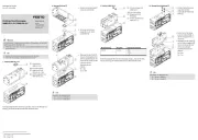
3. Vormontage Kup
p
lung
12189d_2
Ziehen Sie die Kupplung
auseinander und setzen Sie
den Zahnkranz (A) auf eine
der beiden Kupplungsna-
ben 1.
Drehen Sie die Klemm-
schrauben 2 auf.
12189d_3
Platzieren Sie den Zentrier-
ring 5 auf dem Motor.
12189d_6
Schieben Sie die Kupp-
lungsnabe 1 mit der pas-
senden Bohrung auf den
Wellenzapfen (B) der Achse.
12189d_7
Zur genauen Ausrichtung:
Halten Sie den Abstand (X)
ein ( Abschnitt 5).
Drehen Sie die Klemm-
schraube 2 fest.
12189d_4
Schieben Sie die Kupp-
lungsnabe 1 mit der pas-
senden Bohrung auf den
Wellenzapfen (C) des Mo-
tors.
12189d_5
Zur genauen Ausrichtung:
Halten Sie den Abstand (Y)
ein ( Abschnitt 5).
Drehen Sie die Klemm-
schraube 2 fest.
4. Montage EAMM-
A-D32-35A-40A/
P
12189d_8
Befestigen Sie das Kupp-
lungsgehäuse 4 an der
Achse mit allen Schrau-
ben 6.
12189d_9
Schieben Sie den Motor und
die Achse sowie die vor-
montierte Kupplung zusam-
men. Achten Sie dabei auf
die richtige Stellung der
Kupplungsnaben 1 zu-
einander.
Befestigen Sie den Motor
am Kupplungsgehäuse 4
mit allen Schrauben aA.
5. Ausrichtung K
u
pplungsnaben 1
1
1
11
Hinweis
Axialkräfte, die auf die Wellen von Motor und Achse einwirken, können zu
Ausfall von Encoder/Bremse oder zu erhöhtem Verschleiß der Lager führen.
Halten Sie die Abstände X und Y ein.
Motor Achse
9846d_38
EAMM-A- Y
±0,5
[mm] X
±0,5
[mm]
D32-35A-40A 16,3 18,3
D32-35A-40P 19,8 18,3
6. Schraubengrößen und Anziehdrehmomente M
A
1)
EAMM-A- 2
2
2
22 [Nm] 6
6
6
66 [Nm] aA [Nm]
D32-35A-40A M4x12 4 M3x45 1,2 M3x12 1,2
D32-35A-40P
7. Abstützung der Achs-Motor-Kombination
12189d_10
Um Schäden zu vermeiden:
Stützen Sie zusätzlich die
Kombination verspan-
nungsfrei ab.
1)
Toleranzen für nicht tolerierte Anziehdrehmomente M
A
± 20 %
8. Zulässige Achsen/Motoren
Hinweis
Stellen Sie sicher, dass die Motor-Ausgangsleistung die zulässigen Werte
der Achse nicht überschreitet, da bei einigen Kombinationen die Motor-
Ausgangsleistung begrenzt werden muss
( Technische Daten der Achse).
Die zum Anbau zulässigen Motoren und Achsen ergeben sich aus den
Schn
ittstellencodes in der Typenbezeichnung des Bausatzes.
Beispiel: EAMM-A-D32-35A 40A- ist vorgesehen für:
Achs-Schnittstelle -D32 35A
ERMB-20, EHMB-20
Motor-Schnittstelle 40A EMMS-AS-40
Achs-Schnittstelle Ac
hse
D32-35A ERMB-20, EHMB-20
Motor-Schnittstelle Motor
40A EMMS-AS-40
40P EMME-AS-40
2
1
5
4
aA
6
1
A
1
2
2
5
1
C
2
6
4
aA
4
1
1
B
1
2
Assembly instructions (original: de)
8022376
1305b
†‡
Axial kit
EAMM-A-D32-35A-40A/P
Festo SE & Co. KG
Postfach
Germany
+49 711 347-0
www.festo.com
1. Axial kit EAMM-A-D32-35A-40A/P
The kit is intended for connecting an axis to a m
otor in axial configuration to
the driven shaft ( section 8).
Warning
Danger of injury due to uncontrolled movements of the axis!
Before mounting or dismounting:
Make sure that the motor is in a de-energised status.
Observe the safety instructions in the operating instructions for the motor
and axis.
Note
In order to avoid operational malfunctions:
Observe the permissible tightening torques ( section 6).
Do not remove the existing lubricant film from the screws.
Clean the shafts. The coupling 1 only grips dry and grease-free drive
shafts.
Maintain the alignment of the coupling hubs ( section 5).
Make sure that you support the combination ( section 7):
if there are far-protruding and heavy motor fittings
in the event of severe vibrations and oscillation/shock loads.
Each time after disconnecting or twisting the motor:
Start a reference movement of the axis.
2. Parts list EAMM
-A-D32-35A-40A/P
12189d_1
1 Coupling hub
2 Clamping screw
4 Coupling housing
5 Centring ring
6 Screw
aA Screw
(2x)
(2x)
(1x)
(1x)
(4x)
(4x)
3. Preassembly
of the coupling
12189d_2
Pull the coupling apart and
place the ring gear (A) on
one of the two coupling
hubs 1.
Unscrew the clamping
screws 2.
12189d_3
Place the centring ring 5 on
the motor.
12189d_6
Push the coupling hub 1
with the matching hole onto
the drive shaft (B) of the
axis.
12189d_7
For accurate alignment:
Maintain the distance (X)
( section 5).
Tighten the clamping
screw 2.
12189d_4
Push the coupling hub 1
with the matching hole onto
the drive shaft (C) of the mo-
tor.
12189d_5
For accurate alignment:
Maintain the distance (Y)
( section 5).
Tighten the clamping
screw 2.
4. Mounting EAMM
-A-D32-35A-40A/P
12189d_8
Fasten the coupling
housing 4 to the axis with
all screws 6.
12189d_9
Push the motor, the axis and
the pre-assembled coupling
together. When doing this,
observe the correct position
of the coupling hubs in 1
relation to each other.
Fasten the motor to the
coupling housing 4 using
all the screws aA.
5. Alignment of the cou
pling hubs 1
1
1
11
Note
Axial forces on the shafts of motor and axis can result in failure of the enco-
der/brake or increased wear on the bearings.
Maintain the distances X and Y.
Motor Axis
9846d_38
EAMM-A- Y
±0.5
[mm] X
±0.5
[mm]
D32-35A-40A 16.3 18.3
D32-35A-40P 19.8 18.3
6. Screw sizes and tightening torques M
A
1)
EAMM-A- 2
2
2
22 [Nm] 6
6
6
66 [Nm] aA [Nm]
D32-35A-40A M4x12 4 M3x45 1.2 M3x12 1.2
D32-35A-40P
7. Support of the axis-motor combination
12189d_10
To avoid damage:
Also support the
combination so it is free
from tension.
1)
Tolerances for non-toleranced tightening torques M
A
± 20 %
8. Permissible axes/motors
Note
Make sure that the motor power output does not exceed the permissible
values of the axis, since the motor power output must be limited for some
combinations
( Technical data of the axis).
The motors and axes permissible for attac
hment are obtained via the inter-
face code in the type designation of the kit.
Example: EAMM-A-D32-35A 40A- is intended for:
-Axis interface D32 35A
ERMB-20, EHMB-20
Motor interface 40A EMMS-AS-40
Axis interface Axis
D32-35A ERMB-20, EHMB-20
Motor interface Motor
40A EMMS-AS-40
40P EMME-AS-40
2
1
5
4
aA
6
1
A
1
2
2
5
1
C
2
6
4
aA
4
1
1
B
1
2


Produkt Specifikationer

Mærke: Festo
Kategori: Ikke kategoriseret
Model: EAMM-A-D32-35A-40A

Har du brug for hjælp?

Hvis du har brug for hjælp til Festo EAMM-A-D32-35A-40A stil et spørgsmål nedenfor, og andre brugere vil svare dig


Ikke kategoriseret Festo Manualer

Ikke kategoriseret Manualer

Nyeste Ikke kategoriseret Manualer

Kimo

Kimo LR 110 Manual

2 September 2025
HMS Premium

HMS Premium LPD02 Manual

2 September 2025
AVer

AVer E1008 Manual

2 September 2025
Biltema

Biltema 17-547 Manual

2 September 2025
Groen

Groen AH/1E Manual

2 September 2025
ACOPower

ACOPower HY-P30 Manual

2 September 2025
Globe

Globe RG30 Manual

2 September 2025
Neutrik

Neutrik NLT4FXX Manual

2 September 2025