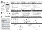
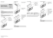
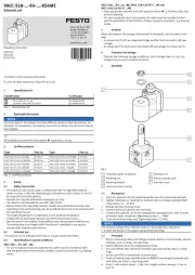
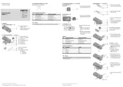
Festo EAPM-L4-SHS Manual


Læs gratis den danske manual til Festo EAPM-L4-SHS (2 sider) i kategorien Ikke kategoriseret. Denne vejledning er vurderet som hjælpsom af 15 personer og har en gennemsnitlig bedømmelse på 3.9 stjerner ud af 8 anmeldelser. Har du et spørgsmål om Festo EAPM-L4-SHS, eller vil du spørge andre brugere om produktet?

Side 1/2
Montageanleitung (de)
753 381 / 2010-10a
†‡
Sensorhalter/Schaltfahne
EAPM-L4-S
Festo SE & Co. KG
Postfach
D-73726 Esslingen
++49/(0)711/347-0
www.festo.com
Bestimmungsgemäß dienen die Bausätze EAPM-L4-S… (Sensorhalter und
Schaltfahne) zum Befestigen und Betreiben von induktiven Näherungsschal-
tern an der Zahnriemenachse ELGR/ELGG oder Führungsachse ELFR.
Warnung
Verletzungsgefahr durch unkontrollierte Bewegungen der Achse.
Vor der Montage bzw. Demontage:
Stellen Sie sicher, dass der Motor in stromlosem Zustand ist.
Beachten Sie die Sicherheitshinweise in den Bedienungsanleitungen von
Motor und Achse.
Vorsicht
Quetsch- bzw. Abschergefahr durch das Verfahren der überstehenden
Schaltfahne 1 über den Sensorhalter 7.
Stellen Sie sicher, dass:
niemand in den Gefahrenbereich hineingreift, durch geeignete Schutz-
maßnahmen.
sich keine Fremdgegenstände im Gefahrenbereich befinden.
13628d_15
1)
1) Alle Montagehinweise zum Lagerdeckel (A) gelten auch für die Mittenstütze der ELGG.
1. Teilelisten
1a. Schaltfahne EAPM-L4-SLS
13628d_1
1 Schaltfahne (1x)
EAPM-L4-SLS
2 Scheibe (2x)
3 Schraube (2x)
M3x8
4 Nutenstein (1x)
5 Schraube (2x)
M3x6
6 Nutenstein (1x)
1b. Sensorhalter EAPM-L4-SHS
13628d_2
7 Sensorhalter (1x)
EAPM-L4-SHS
8 Schraube (2x)
M3x8
9 Nutenstein (1x)
aJ Schraube (2x)
M3x6
aA Nutenstein (1x)
Nicht im Lieferumfang:
13628d_12
aB Näherungsschalter
13628d_13
aC Zahnriemenachse
ELGR/ELGG oder
Führungsachse
ELFR
2. Montagehinweise
13628d_9
Beachten Sie, dass der La-
gerdeckel (A)1) an zwei Sei-
ten einen Überstand (t) ge-
genüber dem Schlitten (B)
hat.
13628d_10
Montieren Sie den Sensor-
halter 7 und die Schalt-
fahne 1 nur in einer der Nu-
ten (C)/(D), da sonst der Nä-
herungsschalter aB nicht
schaltet.
13628d_14
Die Einstellung des Schaltabstandes (s) ist nicht erforderlich.
13628d_11
3. Montage
Info
Wählen Sie je nach Baugröße der Achse die passenden Nutensteine aC
und zugehörigen Schrauben für Schaltfahne 1 und Sensorhalter 7.
EAPM-L4- EL...-35 aC aCEL…-45/-55
SLS 1 5 + 6 3 + 4
SHS 7 aJ + aA 8 + 9
3a. Schaltfahne EAPM-L4-SLS
13628d_3
Schieben Sie den Nuten-
stein 4 6/ je nach Bedarf in
eine der zulässigen Nu-
ten (C)/(D) am Schlitten (B).
13628d_4
Befestigen Sie die Schaltfah-
ne 1 mit den Schrauben
3 5/ und den Scheiben 2
am Nutenstein 4 6/ .
Halten Sie das zulässige An-
ziehdrehmoment ein.
3b. Sensorhalter EAPM-L4-SHS
13628d_5
Schieben Sie den Nuten-
stein 9/aA vollständig in die
gegenüberliegende Nut(D)
der Schaltfahne am Lager-1
deckel (A)1).
13628d_6
Befestigen Sie den Sensor-
halter 7 mit den Schrau-
ben 8/aJ am Nuten-
stein 9/aA.
Halten Sie das zulässige An-
ziehdrehmoment ein.
3c. Näherungsschalter
Info
Wählen Sie die zulässigen induktiven Näherungsschalter aB aus unserem
Katalog www.festo.com/catalogue.
13628d_7
Schieben Sie den Nä-
herungsschalter aB in die
Nut des Sensorhalters 7.
13628d_8
Befestigen Sie den Nä-
herungsschalter aB gemäß
seiner Bedienungsanleitung.
Schieben Sie den Schlit-
ten (B) in die Endlage.
Positionieren Sie die Schalt-
fahne 1 so, dass der Nä-
herungsschalter aB sicher
schaltet.
Hinweis
Um Funktionsstörungen zu vermeiden:
Verhindern Sie eine Fremdbeeinflussung im Nahbereich der Näherungs-
schalter durch andere magnetische oder ferritische Teile als die Schalt-
fahne 1.
2
1
4
3
5
6
7
8
9
aJ
aA
4
/
6
1
4
/
6
7
9
/
aA
aB
aB
aC
aB
1,2 Nm _ 20%
1,2 Nm _ 20%
9
/
aA
A
A
C
C
C
D
B
D
B
2
8
/
aJ
7
3
/
5
1
B
A
1
/
7
/
aB
D
1
/
7
/
aB
B
A
B
1
Schlitten (B) Lagerdeckel (A)1)
1
7
aB
7
1
B
A
Lagerdeckel (A)1) Schlitten (B)
aB
B
A
Assembly instructions (en)
753 381 / 2010-10a
†‡
Sensor bracket/Switch lug
EAPM-L4-S
Festo SE & Co. KG
Postfach
D-73726 Esslingen
++49/(0)711/347-0
www.festo.com
The EAPM-L4-S… kits (sensor bracket and switch lug) are intended for
fastening and operating inductive proximity sensors on the toothed belt axis
ELGR/ELGG or guide axis ELFR.
Warning
Risk of injury due to uncontrolled movements of the axis.
Before assembly or disassembly:
Make sure that the motor is switched off.
Observe the safety notes in the operating instructions for the motor and
axis.
Caution
Danger of crushing or shearing from travel of the protruding switch lug 1
over the sensor bracket 7.
Make sure that:
nobody can place his/her hand in the danger area by providing appropri-
ate protective measures.
no objects lie in the danger area.
13628d_15
1)
1) All mounting instructions for the bearing cap (A) also apply to the central support of the
ELGG.
1. Parts lists
1a. Switch lug EAPM-L4-SLS
13628d_1
1 Switch lug (1x)
EAPM-L4-SLS
2 Washer (2x)
3 Screw (2x)
M3x8
4 Slot nut (1x)
5 Screw (2x)
M3x6
6 Slot nut (1x)
1b. Sensor bracket EAPM-L4-SHS
13628d_2
7 Sensor bracket (1x)
EAPM-L4-SHS
8 Screw (2x)
M3x8
9 Slot nut (1x)
aJ Screw (2x)
M3x6
aA Slot nut (1x)
Not included in scope of deliv-
ery:
13628d_12
aB Proximity sensor
13628d_13
aC Toothed belt axis
ELGR/ELGG or
guide axis
ELFR
2. Assembly notes
13628d_9
Note that the bearing cap
(A)1) has a projection (t) over
the slide (B) on two sides.
13628d_10
Mount the sensor bracket 7
and switch lug only in one 1
of the grooves (C)/(D), since
otherwise the proximity sen-
sor aB will not switch.
13628d_14
It is not necessary to set the switching distance (s).
13628d_11
3. Assembly
Information
Choose the correct slot nuts and matching screws for switch lug 1 and
sensor bracket , depending on the size of the axis 7 aC.
EAPM-L4- EL...-35 aC aCEL…-45/-55
SLS 1 5 + 6 3 + 4
SHS 7 aJ + aA 8 + 9
3a. Switch lug EAPM-L4-SLS
13628d_3
/Push the slot nut 4 6 as
needed into one of the per-
mitted slots (C)/(D) on the
slide (B).
13628d_4
Fasten the switch lug 1 with
screws 3 5/ and wash-
ers 2 onto the slot
nut 4 6/ .
Observe the permitted tight-
ening torque.
3b. Sensor bracket EAPM-L4-SHS
13628d_5
Push the slot nut 9/aA
completely into the opposite
slot (D) of the switch lug 1
on the bearing cap (A)1).
13628d_6
Fasten the sensor bracket 7
with screws 8/aJ onto the
slot nut 9/aA.
Observe the permitted tight-
ening torque.
3c. Proximity sensor
Information
Select the permitted inductive proximity switches aB from our catalogue
www.festo.com/catalogue.
13628d_7
Push the proximity sensor aB
into the slot of the sensor
bracket 7.
13628d_8
Fasten the proximity sen-
sor aB in accordance with the
operating instructions.
Move the slide (B) into the
end position.
Position the switch lug 1 so
that the proximity sensor aB
switches reliably.
Note
In order to avoid functional faults:
Prevent external influence in the vicinity of the proximity sensors caused
by magnetic or ferritic parts other than the switch lug 1.
2
1
4
3
5
6
7
8
9
aJ
aA
4
/
6
1
4
/
6
7
9
/
aA
aB
aB
aC
aB
1.2 Nm _ 20%
1.2 Nm _ 20%
9
/
aA
A
A
C
C
C
D
B
D
B
2
8
/
aJ
7
3
/
5
1
B
A
1
/
7
/
aB
D
1
/
7
/
aB
B
A
B
1
Slide (B) Bearing cap (A)1)
1
7
aB
7
1
B
A
Bearing cap (A)1) Slide (B)
aB
B
A


Produkt Specifikationer

Mærke: Festo
Kategori: Ikke kategoriseret
Model: EAPM-L4-SHS

Har du brug for hjælp?

Hvis du har brug for hjælp til Festo EAPM-L4-SHS stil et spørgsmål nedenfor, og andre brugere vil svare dig