EHAM-MA-E19-25-V3
Adapter plate kit
Festo SE & Co. KG
Ruiter Straße 82
73734 Esslingen
Deutschland
+49 711 347-0
www.festo.com
Assembly instructions
8159352
2021-08
[8159354]
Translation of the original instructions
© 2021 all rights reserved to Festo SE & Co. KG
1 Applicable documents
All available documents for the product
è www.festo.com/sp.
Document Product
User documents Actuators
User documents Modules
Tab. 1: Applicable documents
2 Safety
2.1 Safety instructions
–Before working on the product, switch off the power supply and secure it
against being switched on again.
–Observe further applicable documents.
–Observe tightening torques.
2.2 Intended use
2.2.1 Use
Connection of modules and actuators.
2.2.2 Permissible components
Module Adapter plate kit Actuator
VAEM
VTOF (with mounted module
VAEM)
EHAM-MA-E19-25-V3 EGSC-...-25
EGSC-...-32
EGSK-20
EGSK-26
Tab. 2: Permissible components
3 Additional information
–Contact the regional Festo contact if you have technical problems
è www.festo.com.
–Accessories and spare parts è www.festo.com/catalogue.
4 Product Range Overview
4.1 Scope of delivery
Screw (4x)
The kit contains all the mounting attachments that may be required. Some
mounting attachments will be left over.
4.2 Not in scope of delivery
Actuator (1x)
Mini slide EGSC
Electrical slide EGSK
Modul (1x)
Dispense head VTOF (with mounted
module VAEM)
Valve control module VAEM
5 Assembly
5.1 Preparation
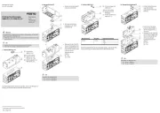
• Observe the labelling on the adapter plate.
Fig. 3: Front side of the adapter plate
Drilled holes for screws
A EGSK-26
B EGSK-20
C EGSC-...-25
D EGSC-...-32
Fig. 4: Rear side of the adapter plate
Drilled holes for centring pins
A EGSK-26
B EGSK-20
C EGSC-...-25
D EGSC-...-32
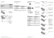
5.2 Connection VTOF/VAEM with EGSC/EGSK
Fig. 5: Mounting adapter plate on actuator
EGSC-...-25 EGSC-...-32 EGSK-20 EGSK-26
2Centring pin ZBS-2 ZBS-4 ZBS-2 ZBS-5
3Screw M3x8 M4x8 M3x8 M4x8
[Nm] 1.2 ± 20% 2.9 ± 10% 1.2 ± 20% 2.9 ± 10%
[P] Drilled hole C-C D-D B-B A-A
[S] Drilled hole C-C D-D B-B A-A
Tab. 3: Screw sizes and tightening torques
1. Position two centring pins in the corresponding drilled holes [S].2
2. Place the adapter plate over the centring pins on the actuator .1 2 6
3. Fasten the adapter plate with the screws over the corresponding drilled1 3
holes [P] on the actuator .6