Festo HMIXB-RP/FP-2 Manual

Festo Ikke kategoriseret HMIXB-RP/FP-2

Læs gratis den danske manual til Festo HMIXB-RP/FP-2 (2 sider) i kategorien Ikke kategoriseret. Denne vejledning er vurderet som hjælpsom af 12 personer og har en gennemsnitlig bedømmelse på 4.3 stjerner ud af 6.5 anmeldelser. Har du et spørgsmål om Festo HMIXB-RP/FP-2, eller vil du spørge andre brugere om produktet?

Side 1/2
Montageanleitung (de)
744 386 / 2009-09NH
†‡
Installationsbausatz
HMIXB-RP/FP-2
Festo SE & Co. KG
Postfach
D-73726 Esslingen
++49/(0)711/347-0
www.festo.com
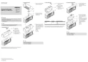
1. Installationsbausatz
1a. HMIXB-RP/FP-2
13916d_2
1 Installationsbausatz
HMIXB-RP/FP-2
1b. Montagebeispiel
13916d_1..Raumportal
2 Antriebseinheit
(! Tabelle)
3 Anbaukomponente
(! Tabelle)
Bestimmungsgemäß dient der Installationsbausatz HMIXB-RP/FP-2 1 als
Basis zum Aufbau von Raumportalsystemen in Duo-Bauweise (X-Module).
Vorsicht
Verletzungsgefahr durch elektrische Spannung.
Verbinden Sie den Bausatz 1 mit dem Schutzleitersystem
! Montageanleitung Erdungsbausatz für HM…63… (HMVS-DL63).
Hinweis
Befestigen Sie eine Mittenstütze 3 mindestens alle 500 mm.
Befestigen Sie einen Bausatz 1 mindestens alle 1000 mm.
Berechnen Sie die dazu benötigte Anzahl y nach folgenden Formeln:
bei Hub 1000 mm: y = 2
bei Hub > 1000 mm: y = Ganzzahl (Hub/1000) +2
Montieren Sie die Antriebe 2 immer zuerst an den Bausatz 1.
Verwenden Sie nur zulässige Energieführungsketten 3 laut Katalog
www.festo.com/catalogue.
Beachten Sie, dass nur Befestigungskombinationen aus der Tabelle
zulässig sind.
Halten Sie die zulässigen Anziehdrehmomente ein (! Tabelle).
Info
Beachten Sie die Montagereihenfolge
! Montageübersicht für HM…63… (HMVS-DL63).
Der Bausatz 1 enthält alle maximal erforderlichen
Befestigungselemente.
Beachten Sie, dass bei einigen Kombinationen Befestigungselemente
übrig bleiben.
2. Montage an Antriebseinheit 2
2
2
22
Wählen Sie die Befestigungselemente (Schrauben, usw.) für Ihre
Kombination (! Tabelle).
Beachten Sie die Bildzuordnung für Ihre Kombination (! Tabelle).
Bild 1
13916d_3
2 Linearantrieb
DGE-63-…-ZR-KF
3 Mittenstütze
MUP-63
Befestigen Sie eine
Mittenstütze 3 mindestens
alle 500 mm.
Bild 2
13916d_4
1 Installationsbausatz
HMIXB-RP/FP-2
2 Linearantrieb
DGE-63-…-ZR-KF
Befestigen Sie einen
Bausatz 1 mindestens
alle 1000 mm.
1)
2
1) Toleranzen für nicht tolerierte Anziehdrehmomente MA
MA > 1 Nm: ± 20%
2) wahlweise
3. Montage an Anbaukomponente 3
3
3
33
Wählen Sie die Befestigungselemente (Schrauben, usw.) für Ihre
Kombination (! Tabelle).
Beachten Sie die Bildzuordnung für Ihre Kombination (! Tabelle).
Bild 3
Bild 3a
13916d_5
1 Installationsbausatz
HMIXB-RP/FP-2
2 Linearantrieb
DGE-63-…-ZR-KF
3 Auflageprofil
HMIA-E05/-E072)
Bild 3b
13916d_5
1 Installationsbausatz
HMIXB-RP/FP-2
2 Linearantrieb
DGE-63-…-ZR-KF
3 Auflageprofil
HMIA-E10
Raumportal
3289d_5
1
1
2
3
B
2
HMIXB-RP/FP-2
DGE-...-ZR-KF DGE-...-ZR-KF
63 63
MUP-63 HMIA-E05/-E07
2)
HMIA-E10
1 2 3a 3b
M
A1)
[Nm]
M5x10 6 2x 4x
M8x16 24 4x
B5,3 2x 4x
MUP- 32/40 1x 2x
NST-HMV-8-2-M8 2x
M8x18 24 4x
NST-HMV-8-2-M8 2x
1 Bausatz
DGE-...-ZR-KF
HMIXB-RP/FP-2
Bild
D Zylinderschraube nach DIN 912
63
Befestigungselemente im Lieferumfang der Anbaukomponenten
A Zylinderschraube nach DIN 912
B Scheibe nach DIN 125
E Nutenstein
2 Antriebseinheit
3 Anbaukomponente
C Nutenstein
2
E
3
A
B
C
1
C
3
1
A
A
2
C
D
3
1
2
Assembly instructions (en)
744 386 / 2009-09NH
†‡
Installation kit
HMIXB-RP/FP-2
Festo SE & Co. KG
Postfach
D-73726 Esslingen
++49/(0)711/347-0
www.festo.com
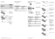
1. Installation kit
1a. HMIXB-RP/FP-2
13916d_2
1 Installation kit
HMIXB-RP/FP-2
1b. Assembly example
13916d_1..Raumportal
2 Drive unit
(!Table)
3 Attachment component
(!Table)
The installation kit HMIXB-RP/FP-2 1 is intended for use as a basis for the
setup of 3D gantry systems in duo design (X modules).
Caution
Danger of injury due to electric voltage.
Connect the kit 1 with the protective conductor system
! Assembly instructions earthing kit for HM…63… (HMVS-DL63).
Note
Attach a central support 3 at least every 500 mm.
Attach a basic kit 1 at least every 1000 mm.
Calculate the required quantity y using the following formulas:
where stroke length 1000 mm: y = 2
where stroke length > 1000 mm: y = whole-number (stroke/1000) +2
Always mount the drives 2 to the mounting kit 1 first.
Use only permitted energy chains 3 as specified in the catalogue
www.festo.com/catalogue.
Note that only the fastening combinations shown in the table are
permissible.
Maintain the permitted tightening torques (!Table).
Information
Follow the mounting sequence
! Mounting overview for HM…63… (HMVS-DL63).
The kit 1 includes all maximally required mounting attachments.
Note that mounting components may be left over with some
combinations.
2. Mounting on drive unit 2
2
2
22
Select the mounting components (screws etc. ) for your combination
(! Table).
Observe the reference to the figures for your combination (! Table).
Fig. 1
13916d_3
2 Linear drive
DGE-63-…-ZR-KF
3 Central support
MUP-63
Attach a central support 3 at
least every 500 mm.
Fig. 2
13916d_4
1 Installation kit
HMIXB-RP/FP-2
2 Linear drive
DGE-63-…-ZR-KF
Attach an installation kit 1
at least every 1000 mm.
1)
2
1 ) Tolerance for non-toleranced tightening torques M A
MA > 1 Nm: ± 20%
2 ) either
3. Mounting on attachment component 3
3
3
33
Select the mounting components (screws etc. ) for your combination
(!Table).
Observe the reference to the figures for your combination (!Table).
Fig. 3
Fig. 3a
13916d_5
1 Installation kit
HMIXB-RP/FP-2
2 Linear drive
DGE-63-…-ZR-KF
3 Support profile
HMIA-E05/-E072)
Fig. 3b
13916d_5
1 Installation kit
HMIXB-RP/FP-2
2 Linear drive
DGE-63-…-ZR-KF
3 Support profile
HMIA-E10
3D gantry
3289d_5
1
1
2
3
B
2
HMIXB-RP/FP-2
DGE-...-ZR -KF DGE-...-ZR -KF
63 63
MUP-63 HMIA-E05/-E07 2) HMIA-E10
1 2 3a 3b
MA
1) [Nm ]
M 5x1 0 6 2x 4x
M 8x1 6 24 4x
B5,3 2x 4x
M UP- 3 2/40 1x 2x
NST-HM V-8-2-M8 2x
M 8x1 8 24 4x
NST-HM V-8-2-M8 2x
E Slot nut
2 Drive unit
3 Attachment component
C Slot nut
1 Kit
DGE-...-ZR -KF
HMIXB-RP/FP-2
Fig.
D Socke t head screw as per DIN 912
63
M ounting components included with attachm ent components
A Socket head scre w as per DIN 912
B Washe r as per DIN 12 5
2
E
3
A
B
C
1
C
3
1
A
A
2
C
D
3
1
2


Produkt Specifikationer

Mærke: Festo
Kategori: Ikke kategoriseret
Model: HMIXB-RP/FP-2

Har du brug for hjælp?

Hvis du har brug for hjælp til Festo HMIXB-RP/FP-2 stil et spørgsmål nedenfor, og andre brugere vil svare dig


Ikke kategoriseret Festo Manualer

Ikke kategoriseret Manualer

Nyeste Ikke kategoriseret Manualer

Turbo Air

Turbo Air TBC-65SB-N6 Manual

2 September 2025
XPower

XPower BR-282A Manual

2 September 2025
Grunkel

Grunkel SAN-GRILLNG Manual

2 September 2025
AVer

AVer DL10 Manual

2 September 2025
Rigol

Rigol HDO1204 Manual

2 September 2025
XPower

XPower A-2B Manual

2 September 2025