Festo HMVZ-3 Manual


Læs gratis den danske manual til Festo HMVZ-3 (2 sider) i kategorien Ikke kategoriseret. Denne vejledning er vurderet som hjælpsom af 21 personer og har en gennemsnitlig bedømmelse på 5.0 stjerner ud af 11 anmeldelser. Har du et spørgsmål om Festo HMVZ-3, eller vil du spørge andre brugere om produktet?

Side 1/2
Montageanleitung (de)
738 927 / 2008-07c
†‡
Grundbausatz
HMVZ-3/-4
Festo SE & G Co. K
Postfach
D-73726 Esslingen
++49/(0)711/347-0
www.festo.com
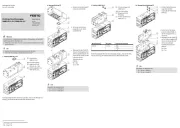
1. Grundbausatz
1a. HMVZ-
7683d_17
1 Grundbausatz
HMVZ-3
2 Grundbausatz
HMVZ-4
1b. Montagebeispiel
7683d_3
7683d_4
Bestimmungsgemäß dient der
Grundbausatz HMVZ 1 / 2
beim Aufbau von Portal-
systemen in Mono- bzw. Duo-
Bauweise als Schnittstelle zwi-
schen den Y-Achsen der Bau-
größe 25/-40 und den
Z-Achsen 3.
Warnung
Verletzungsgefahr durch elektrische Spannung.
Nach der Montage:
Verbinden Sie den Grundbausatz mit dem Schutzleitersystem
! Montageanleitung Erdungsbausatz.
Hinweis
Beachten Sie:
dass nur Befestigungskombinationen aus der Tabelle zulässig sind.
Verwenden Sie nur zulässige Energieführungsketten 4 (! 4c.)
laut Katalog ! www.festo.com/catalogue.
Info
Die Grundbausätze 1 und 2 enthalten alle maximal erforderlichen Be-
festigungselemente.
Beachten Sie:
dass bei einigen Kombinationen Befestigungselemente übrig bleiben.
Montieren Sie den Grundbausatz immer zuerst an die Z-Achse 3.
2. Schnittstellen bei HMVZ-3 für Z-Achse 3
3
3
33
2a. Auslegerachse DGEA-18-ZR
7683_6_j
1 Grundbausatz
HMVZ-3
3 Auslegerachse
DGEA-18-ZR
Montieren Sie die Z-Achse 3
zunächst ohne Motor (w) auf
den Grundbausatz 1.
Nach der Montage auf den
Adapterbausatz
HMVS-DL25/-DL40 (! 4a.):
Befestigen Sie den Motor (w)
an der Z-Achse 3.
2b. Spindelachse DGE-25-SP
7683_7_j
1 Grundbausatz
HMVZ-3
3 Spindelachse
DGE-25-SP
2c. Linearmodul HMP/HME
7683d_8_j
1 Grundbausatz
HMVZ-3
3 Linearmodul
HMP-16/-20
HME-16
3. Schnittstellen bei HMVZ-4 für Z-Achse 3
3
3
33
3a. Spindelachse DGE-40-SP
7683d_9_j
2 Grundbausatz
HMVZ-4
3 Spindelachse
DGE-40-SP
Montieren Sie die Z-Achse 3
ohne Schaltfahne (x) auf den
Grundbausatz 2.
Nach der Montage auf den
Adapterbausatz
HMVS-DL25/-DL40 (! 4a.):
Befestigen Sie die Schalt-
fahne (x) an der Z-Achse 3.
3b. Auslegerachse DGEA-25-ZR
7683d_10_j
2 Grundbausatz
HMVZ-4
3 Auslegerachse
DGEA-25-ZR
Montieren Sie die Z-Achse 3
zunächst ohne Motor (y) auf
den Grundbausatz 2.
Nach der Montage auf den
Adapterbausatz
HMVS-DL25/-DL40 (! 4a.):
3c. Linearmodul HMPL
7683d_11j
2 Grundbausatz
HMVZ-4
3 Linearmodul
HMPL-16/-20
Bei Alternative 1:
Montieren Sie die Z-Achse 3
zunächst ohne Klemmpatro-
ne (z) auf den Grundbausatz
2.
Nach der Montage
Auf den Adapterbausatz
HMVS-DL25/-DL40 (! 4a.):
Befestigen Sie die Klemm-
patrone (z) an der
Z-Achse 3.
1
1) MA= Anziehdrehmoment; Toleranzen bei MA > 1 Nm: ± 20%
2) Verwenden Sie an der Aussparung (F) des Grundbausatz HMVZ-4 zwei Zylinderschrau-
ben (B) mit niedrigem Kopf (keine Zentrierhülse).
4. Schnittstellen für Anbaukomponenten 4
4
4
44
4a. Adapterbausatz HMVS-DL
7683d_13
1 / 2
Grundbausatz
HMVZ-3/-4
4 Adapterbausatz
HMVS-DL25/-DL40
Lesen Sie dazu die Mon-
tageanleitung für den Adap-
terbausatz HMVS-DL25/-
DL40.
4b. Klemmschellen MKRS-…-B
7683d_14
1 / 2
Grundbausatz
HMVZ-3/-4
4 Klemmschellen
MKRS-16.5/-23/-29-B3)
4c. Energieführungsketten
7683d_15
1 / 2
Grundbausatz
HMVZ-3/-4
4 Energieführungskette
3)
Hinweis
Nach der Montage:
Verfahren Sie die Achsen von Hand und überprüfen Sie dabei die In-
stallation bzw. das leichte Abrollen der Energieführungsketten.
45
3) Bei Mono-Systemen mit SPC und bei Duo-Systemen müssen diese Installationselemente
der Z-Achsen am Installationsbausatz HMIZB-E03 angebunden werden.
4) Bei DGE-40-... entfallen die Befestigungsschrauben im Bereich des Schlittens.
5) Bei Alternative 2: Befestigung an Klemmpatrone.
2
1
/
2
3289d_4
1
/
2
3
3
3289d_5
D
C
3
1
A
C
A
3
1
x
C
A
3
2
2
2
3
3
A
C
z
1
Linien
p
ortal
Raumportal
2a. 2b. 3a. 3b. 3c. 4b. 4c.
Bausatz 1 2
HMVZ-3 HMVZ-4
DGEA- DGE- HMP- HME- DGE- DGEA- HMPL- MKRS- E-Kette
3)
18-ZR 25-SP 16/20 16 40-SP 25-ZR 16/20 -B3
3)
M
A
1)
[Nm]
M4x16 3 2x
M5x12 8x 8x
M5x16 6x 6x 8x 10x
4)
8x
2) 4)
M5x45 4x
5)
M6x14
M6x16 6x 6x
M5x14 2x
2) 4)
ZBH-9 2x 2x 2x 2x 2x 2x 2x 4x 3x
2)
NSTL-25 2x 2x
M6x16 10 2x
4a.
E Senkschrauben nach DIN 7991
A Zylinderschrauben nach DIN 912
Schnittstelle
6
3
HMVZ-3
B Zylinderschrauben nach DIN 6912
HMVS-
2c.
C Zentrierhülsen
D Nutensteine
DL
Z-Achse /
Anbaukomponenten
1 / 2
10
2
HMVZ-4
3
1
4
HMVZ-3
-4
A
C
D
w
3
1
A
y
C
3
2
1
/
2
C
A
Alternative 1 Alternative 2
(F)
(F)
4
B
A
1
/
2
4
D
1
/
2
4
Assembly instructions (en)
738 927 / 2008-07c
†‡
Basic kit
HMVZ-3/-4
Festo SE & G Co. K
Postfach
D-73726 Esslingen
++49/(0)711/347-0
www.festo.com
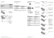
1. Basic kit
1a. HMVZ-
7683d_17
1 Basic kit
HMVZ-3
2 Basic kit
HMVZ-4
1b. Assembly example
7683d_3
7683d_4
The basic kit HMVZ 1 / 2 is in-
tended for use as an interface
between size 25/-40 Y-axes and
Z-axes 3 when setting up gan-
try systems in mono or duo de-
sign.
Warning
Danger of injury due to electric voltage.
After assembly:
Connect the basic kit with the protective conductor system
! assembly instructions earthing kit.
Note
Note:
that only the fastening combinations shown in the table are permissible.
Use only permitted energy chains 4 (! 4c.)
as specified in the catalogue ! www.festo.com/catalogue.
Information
The basic kits 1 and 2 contain all necessary fastening components.
Note:
that mounting components may be left over with some combinations.
Always mount the basic kit to the Z-axes 3 first.
2. Interfaces with HMVZ-3 for axis 3
3
3
33
2a. Cantilever axis DGEA-18-ZR
7683_6_j
1 Basic kit
HMVZ-3
3 Cantilever axis
DGEA-18-ZR
Mount the Z-axis 3
at first without motor (w)
onto the basic kit 1.
After mounting onto the adapter
kit HMVS-DL25/-DL40 (! 4a.):
Fasten the motor (w) onto
the Z-axis 3.
2b. Spindle axis DGE-25-SP
7683_7_j
1 Basic kit
HMVZ-3
3 Spindle axis
DGE-25-SP
2c. Linear module HMP/HME
7683d_8_j
1 Basic kit
HMVZ-3
3 Linear module
HMP-16/-20
HME-16
3. Interfaces with HMVZ-4 for axis Z- axis 3
3
3
33
3a. Spindle axis DGE-40-SP
7683d_9_j
2 Basic kit
HMVZ-4
3 Spindle axis
DGE-40-SP
Mount the Z-axis 3 at
first without switch lug (x)
onto the basic kit 2.
After mounting onto the adapter
kit HMVS-DL25/-DL40 (! 4a.):
Fasten the switch lug (x)
onto the Z-axis 3.
3b. Cantilever axis DGEA-25-ZR
7683d_10_j
2 Basic kit
HMVZ-4
3 Cantilever axis
DGEA-25-ZR
Mount the Z-axis 3 at first
without motor (y) onto the
basic kit 2.
After mounting onto the adapter
kit HMVS-DL25/-DL40 (! 4a.):
Fasten the motor (y) onto
the Z-axis 3.
3c. Linear module HMPL
2 Basic kit
HMVZ-4
3 Linear module
HMPL-16/-20
With alternative 1:
Mount the Z-axis 3 at first
without clamping car-
tridge (z) onto the basic kit
2.
After mounting onto the adapter
kit HMVS-DL25/-DL40 (! 4a.):
Fasten the clamping cartridge
onto the Z-axis 3.
1) MA= Tightening torque; Tolerance at MA > 1 Nm: ± 20%
2) Use two socket head screws (B) with low head on the recess (F) of basic kit HMVZ-4.
4. Interfaces for attachment components 4
4
4
44
4a. Adapter kit HMVS-DL
7683d_13
1 / 2
Basic kit
HMVZ-3/-4
4 Adapter kit
HMVS-DL25/-DL40
Refer to the assembly in-
structions for the adapter kit
HMVS-DL25/-DL40 to this
end.
4b. Retaining clips MKRS-…-B
7683d_14
1 / 2
Basic kit
HMVZ-3/-4
4 Retaining clips
MKRS-16.5/-23/-29-B3)
4c. Energy chain
7683d_15
1 / 2
Basic kit
HMVZ-3/-4
4 Energy chain3)
Note
After mounting:
Advance the axes manually, and check for correct installation of the
energy chains, i.e. smooth rolling.
45
3) These Z-axis installation elements must be attached onto installation kit HMIZB-E03 for
mono-systems with PLC and for duo-systems.
4) Retaining screws are not used in proximity on the slide with DGE-40-....
5) With alternative 2: Attachment to clamping cartridge.
2
1
/
2
3289d_4
1
/
2
3
3
3289d_5
D
C
3
1
A
C
A
3
1
x
C
A
3
2
2
2
3
3
A
C
z
1
Linear gantr
y
3D gantry
A
C
D
w
3
1
A
y
C
3
2
1
/
2
C
A
Alternative 1 Alternative 2
(F)
(F)
4
B
A
1
/
2
4
D
1
/
2
4
2.a. 2.b. 2.c. 2.c. 3.a. 3.b. 3.c. 4.b. 4.c.
Kit 1 2
HMVZ-3 HMVZ-4
DGEA- DGE- HMP- HME- DGE- DGEA- HMPL- MKRS- E-chain
3)
18-ZR 25-SP 16/20 16 40-SP 25-ZR 16/20 -B33)
MA
1) [Nm]
M4x16 3 2x
M5x12 8x 8x
M5x16 6x 6x 8x 10x 4) 8x2) 4)
M5x45 4x5)
M6x14
M6x16 6x 6x
M5x14 2x 2) 4)
ZBH-9 2x 2x 2x 2x 2x 2x 2x 4x 3x2)
NSTL-25 2x 2x
M6x16 10 2x
HMVZ-3
/
-4
DL…
Z-axis /
attachment component
1 / 2
10
2
HMVZ-4
3
1
C Centring sleeves
D Slot nuts
4.a.
E Countersunk screws as per DIN 7991
A Socket head screws as per DIN 912
Interface
6
3
HMVZ-3
B Socket head screws as per DIN 6912
HMVS-
4


Produkt Specifikationer

Mærke: Festo
Kategori: Ikke kategoriseret
Model: HMVZ-3

Har du brug for hjælp?

Hvis du har brug for hjælp til Festo HMVZ-3 stil et spørgsmål nedenfor, og andre brugere vil svare dig