Festo MS6-WPG Manual


Læs gratis den danske manual til Festo MS6-WPG (2 sider) i kategorien Ikke kategoriseret. Denne vejledning er vurderet som hjælpsom af 25 personer og har en gennemsnitlig bedømmelse på 3.8 stjerner ud af 13 anmeldelser. Har du et spørgsmål om Festo MS6-WPG, eller vil du spørge andre brugere om produktet?

Side 1/2
Translation of the original instructions
1 Applicable documents
All available documents for the product www.festo.com/pk.è
Document Product Contents
Instructions MSE6-C2M Operating, Control and Condition Monit-
oring Module
Instructions MSE6-D2M Operating, Energy Efficiency Module
Description MSE6-E2M Assembly, Installation, Commissioning,
Energy Efficiency Module
Tab. 1
2 Safety
2.1 Safety instructions
Only assemble the product on components that are in a condition to be safely
operated.
2.2 Intended use
Wall mounting of maintenance device modules and service unit
3 Product range overview
3.1 Scope of delivery
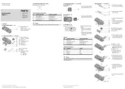
Wall mounting kit MS6-WPG:
1Wall mounting(1x)
2Module connector(1x)
3O-ring(1x)
Fig. 1
3.2 Not in scope of delivery
Module connector MS6-MV-EX:
4Module connector(1x)
(rear)
5Module connector(1x)
(front)
6O-ring(1x)
Fig. 2
4 Mounting
4.1 Mounting positions
Depending on the configuration, mount the wall mounting kit between the fol-
lowing service units and the service device modules.
Product Type Mounting position
Wall mounting kit MS6-WPG black box
Service unit MSE6-D2M [A]
MSE6-E2M [B]
MSE6-C2M...(-M) [C]
Service device module MS6-... [D]
MS6-SV-D [E]
Tab. 2
4.1.1 Positions with service unit[A]/[B] and modules[D]
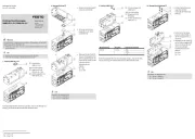
Fig. 3
4.1.2 Positions with service unit[A]/[B] and modules[D]/[E]
Fig. 4
4.1.3 Positions with service unit[C] and modules[D]
Fig. 5
4.1.4 Positions with service unit[C] and modules[D]/[E]
Fig. 6
4.2 Assembly
NOTICE!
Incorrect electromagnetic compatibility if incorrect module connectors are moun-
ted.
Use only module connector MS6-MV-EX.
Mounting with example of MSE6-E2M[B]:
Fig. 7
1. Remove earth cable[F] from earth terminal[G].
2. Remove module connector from the wall mounting .2 1
3. Remove sub-base[H] from the service unit[B].
8105041
MS6-WPG
Wall mounting-Set
8105041
2019-01b
[8105043]
Instructions|Assembly
Festo SE & Co. KG
Ruiter Straße 82
73734 Esslingen
Germany
+49 711 347-0
www.festo.com
Fig. 8
Place O-ring between the service unit[B] and the service device mod-6
ule[D].
Fig. 9
Mount module connector on the wall mounting . Tightening torque:2 1
1.2Nm ± 10 %
Fig. 10
Place O-ring between the two service device modules[D].3
Fig. 11
Mount module connector on the module connector . Tightening torque:5 4
1.2Nm ± 10 %
Fig. 12
1. Place wall mounting on the service device module[D].1
2. Place sub-base[H] on the interface of the service device module[D].
Fig. 13
Mount module connector on the wall mounting . Tightening torque:2 1
1.2Nm ± 10 %
Fig. 14
1. If necessary, replace the included earth cable[F] with a longer earth cable.
2. Connect the earth cable[F] to the earth point[G] again. Tightening torque:
2Nm ± 10 %


Produkt Specifikationer

Mærke: Festo
Kategori: Ikke kategoriseret
Model: MS6-WPG

Har du brug for hjælp?

Hvis du har brug for hjælp til Festo MS6-WPG stil et spørgsmål nedenfor, og andre brugere vil svare dig


Ikke kategoriseret Festo Manualer

Ikke kategoriseret Manualer

Nyeste Ikke kategoriseret Manualer

Kimo

Kimo LR 110 Manual

2 September 2025
HMS Premium

HMS Premium LPD02 Manual

2 September 2025
AVer

AVer E1008 Manual

2 September 2025
Biltema

Biltema 17-547 Manual

2 September 2025
Groen

Groen AH/1E Manual

2 September 2025
ACOPower

ACOPower HY-P30 Manual

2 September 2025
Globe

Globe RG30 Manual

2 September 2025
Neutrik

Neutrik NLT4FXX Manual

2 September 2025