Festo SPAN Manual


Læs gratis den danske manual til Festo SPAN (6 sider) i kategorien Ikke kategoriseret. Denne vejledning er vurderet som hjælpsom af 8 personer og har en gennemsnitlig bedømmelse på 4.9 stjerner ud af 4.5 anmeldelser. Har du et spørgsmål om Festo SPAN, eller vil du spørge andre brugere om produktet?

Side 1/6
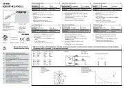
Pressure sensor SPAN
Festo SE & Co. KG
Ruiter Straße 82
73734 Esslingen
Germany
+49 711 347-0
www.festo.com
Operating instructions 8035566
2017-11a
[8035568]
Translation of the original instructions
Pressure sensor SPAN English. . . . . . . . . . . . . . . . . . . . . . . . . . . . . . . . . . . . . . . . . .
For all available product documentation è www.festo.com/pk
1 Product description
The operating instructions describe the entire function range. The function range is
limited, depending on the product variant.
Note
You can find detailed specifications for the product, the device description file
(IODD) with a description of the IO-Link parameters and the declaration of con
formity at: è www.festo.com/sp.
1.1 Overview
1
2
3
456
1Display
2Electrical connection
3Pneumatic connection
4B-key
5Edit button
6A-key
Fig. 1 Representation of other variants can deviate from this
1.2 Characteristics
Characteristic Value Description
Type SPAN Pressure sensor
Pressure
measuring range
-B2, -B11, -P025, -P05, -P1, -P2,
-P6, -P10, -P12, -P16, -V025,
-V05, -V1
è Technical data
Supply port R Relative pressure
Pneumatic port -G18, -R18, N18, -M5,
-Q4,
Thread Gx x x, R , NPT , M5
Push-in connector 4 mm
Thread type
M
F
None
Male thread
Female thread
Electrical
output 1
-PNLK
-PN
Switching output PNP / NPN / IO-Link
PNP / NPN
Electrical
output 2
-PNVBA
-PN
PNP / NPN / 0…10 V / 1…5 V / 4…20 mA
PNP / NPN
Electrical
connection
-L1 Plug connector, design L1
Certificate
+T
Without
With inspection report
Fig. 2
2 Safety
Intended use
The pressure sensor SPAN is intended for monitoring pressure of compressed air
and inert gases in the piping.
General safety information
Only use the product in its original status, without any unauthorised modifications.
Only use the product if it is in an excellent technical status.
The product is intended for use in industrial environments. Measures may need
to be implemented in residential areas for radio interference suppression.
Take into consideration the ambient conditions at the location of use.
Operate the product only with compressed air of the specified air quality class
(è Technical data).
Observe the specifications on the rating plate.
Comply with all applicable national and international regulations.
Disposal
Observe the local specifications for environmentally friendly disposal.
Range of applications and certifications
In connection with the UL marking on the product, the information of this section is
also applicable for compliance with the certification conditions of Underwriters
Laboratories Inc. (UL) for the U.S.A. and Canada.
UL approval information
Product category code QUYX (USA)
QUYX7 (Canada)
File number E322346
Considered standards UL 610101
C22.2 No. 610101
UL mark
Fig. 3
Unit shall be supplied by a power source which complies with the requirements of
a limited-energy circuit in accordance with IEC/EN/UL/CSA 61010-1 or a Limited
Power Source (LPS) in accordance with IEC/EN/UL/CSA 60950-1 or IEC/EN/UL/
CSA 62368-1 or a Class 2 circuit in accordance with NEC or CEC.
3 Function and application
The sensor converts pneumatic pressure values (relative pressure) into electrical
signals, which can be used for control or regulating functions. Measurements are
carried out using a piezoresistive sensor element with a following electronic evalu
ation unit. Interfacing to the higher-level system is provided by 1 or 2 switching
outputs, an optional analogue output and an optional IO-Link interface.
The switching outputs can be configured for monitoring of a threshold value,
a pressure range or a differential pressure. The outputs can be set as PNP or NPN
and normally open (NO) or normally closed (NC). Via the IO-Link interface, process
values can be read out and parameters changed and transmitted to additional
devices.
3.1 Operating statuses
Operating status Function
RUN mode Basic status after the operating voltage is switched on
Display of the current measured value
SHOW mode Display of the current settings
EDIT mode Setting or modification of parameters
TEACH mode Acceptance of the current measured value to determine switching
points
Fig. 4
3.2 Switching functions
Threshold value comparator for monitoring of a pressure threshold _
Function NO (normally open) NC (normally closed)
Switching function:
1 switching point (SP)
TEACH mode:
2 teach-in points (TP1, TP2)
SP = ½ (TP1+TP2) TP1 TP2
HY
1
0
Out
p
SP TP1 TP2
SP
HY
1
0
Out
p
Fig. 5
Window comparator for monitoring of a pressure range _|¯|_
Function NO (normally open) NC (normally closed)
Switching function:
2 Switching points
(SP.Lo, SP.Hi)
TEACH mode1):
2 teach-in points (TP1, TP2)
TP1 = SP.Lo, TP2 = SP.Hi
HY HY
TP1=SP.Lo TP2=SP.Hi
1
0
Out
p
HY HY
TP1=SP.Lo TP2=SP.Hi
1
0
Out
p
1) SP.Lo = smaller pressure/vacuum value, SP.Hi = larger pressure/vacuum value, dependent on the
Teach sequence
Fig. 6
Auto difference monitoring d_|¯|_
This funciton permits monitoring of a pressure value for constancy.
If the applied pressure is constant in the range between [SP.Lo] and [SP.Hi], the refer
ence pressure PRef is automatically determined. The result is a switching operation at
the output. The signal change signals the start of pressure monitoring.
If the pressure remains in the monitoring range [d.SP] around PRef, the pressure is
stable. When the monitoring range is left (e.g. caused by a leakage in the system),
the output switches back.
1 2
3
1Reference value is determined
2Measured value deviates by [d.SP] from the reference value
3Monitoring area
Fig. 7
The parameters [SP.Lo], [SP.Hi], [t.obS] and [d.SP] can be configured by the user.
The greater [t.obS] is set, the more constant the pressure signal must be to establish
the reference value PRef.
Function NO (normally open) NC (normally closed)
Switching function:
2 switching points (SP.Lo,
SP.Hi) for setting the valid
work range
1 switching point (d.SP)
for determination of
the monitoring area
TEACH mode1):
2 teach-in points (TP1, TP2)
TP1 = SP.Lo, TP2 = SP.Hi
SP.Lo PRef SP.Hi
d.SP
1
0
Out
p
1
SP.Lo PRef SP.Hi
d.SP
0
Out
p
1) SP.Lo = smaller pressure value, SP.Hi = larger pressure value, independent of the Teach sequence
Fig. 8
4 Installation
Note
Installation and commissioning are to be carried out only by qualified personnel
in accordance with the operating instructions.
Remove all transport packaging. The material used in the packaging has been
specifically chosen for its recyclability.
4.1 Mechanical and pneumatic
Note
An unfavourable mounting position can impair the function of the product.
Mount the sensor so that no condensate from the compressed air lines can
gather in the device.
Install the sensor so that it cannot be heated above the maximum permissible
operating temperature (plan for convection possibilities).
SPAN-...-G18M/R18M/N18M Mounting bracket
Seal connecting thread.
max. 10 Nm
13 mm
max. 0,5 Nm
@ 3,3 mm
Fig. 9 Example with G18M Fig. 10 Example with SAMH-PU-A-. Fastening
SAMH-PN-W correspondingly
Front panel use SAMH-PN-F
Size of the front panel cut-out in mm è Fig. 11.
Fasten panel frame to the sensor.
Guide sensor from the front into the cut-out on the front panel.
Attach the clamping element and press until it catches.
31 -0.4
31 -0.4
X
31 -0.4
X=31*n+3.5*(n-1)
s=max. 5 mm
1
2
1Panel frame
2Clamping element
Fig. 11 Fig. 12
4.2 Electrical
Warning
Use only power sources which guarantee reliable electrical isolation of the oper
ating voltage in accordance with IEC/EN 60204-1. Consider also the general
requirements for PELV circuits in accordance with IEC/EN 60204-1.
Connect sensor.
Consider the maximum permissible line length: 30 m (20 m for IO-Link).
Pin Colour1) Allocation Plug L1
1 Brown (BN) Operating voltage +24 V DC 1 2 3 4
2 Black (BK) Switching output OutA or IO-Link
(C/Q line)
3 White (WH) Switching output OutB or
analogue output (pressure
signal InA)
4 Blue (BU) 0 V
1) Colours apply for connecting cables NEBS-L1... or electrical adapter SASC-P4... with NEBU-M8...
Fig. 13
Circuit diagrams
SPAN-...-PNLK-PNVBA SPAN-...-PN-PN
Fig. 14 Fig. 15


Produkt Specifikationer

Mærke: Festo
Kategori: Ikke kategoriseret
Model: SPAN

Har du brug for hjælp?

Hvis du har brug for hjælp til Festo SPAN stil et spørgsmål nedenfor, og andre brugere vil svare dig


Ikke kategoriseret Festo Manualer

Ikke kategoriseret Manualer

Nyeste Ikke kategoriseret Manualer