Festo VABE-P5-C Manual


Læs gratis den danske manual til Festo VABE-P5-C (2 sider) i kategorien Ikke kategoriseret. Denne vejledning er vurderet som hjælpsom af 42 personer og har en gennemsnitlig bedømmelse på 4.4 stjerner ud af 21.5 anmeldelser. Har du et spørgsmål om Festo VABE-P5-C, eller vil du spørge andre brugere om produktet?

Side 1/2
Montageanleitung (Original: de)
8021977
1211NH
†‡
Druck-/Zwischeneinspeiseplatte,
Endplatte
VABF-P5-...A3/VABE-P5-C
Festo SE & Co. KG
Postfach
D-73726 Esslingen
+49 711 347-0
www.festo.com
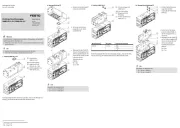
1. Teileliste
18262d_1
Druckeinspeiseplatte
VABF-P5-P3A3-...
1 Platte
2 Dichtung
3 Schraube M5x12
(1x)
(1x)
(4x)
18262d_3
Endplatte
VABE-P5-C
1 Platte
2 Dichtung
3 Schraube M5x12
(1x)
(1x)
(4x)
18262d_2
Zwischeneinspeiseplatte
VABF-P5-P1A3-...
1 Platte
2 O-Ring
3 Schraube M6x20
4 Nutenstein
(1x)
(1x)
(2x)
(2x)
1826
2d_6 Nicht im Lieferumfang:
5 Profilleiste (1x)
IPM-PN-08-40x80-AL
Bestimmungsgemäß dient:
die Druckeinspeiseplatte als seitlicher Druckluftanschluss und als Abdich-
tung der Profilleiste
die Endplatte als Abdichtung der Profilleiste
die Zwischeneinspeiseplatte als frontaler zusätzlicher Druckluftanschluss
der Profilleiste.
Hinweis
Wählen Sie weiteres Zubehör aus dem Katalog
(z. B. Montageplatte VAME-P5-MK).
Zur Montage der Montageplatten ( zugehörige Montageanleitung).
2. Vormontage (Bei der Befestigung einer Zwischeneinspeiseplatte)
Hinweis
Um eine optimale Druckluftversorgung bei der Verwendung einer Zwischen-
einspeiseplatte zu gewährleisten.
Beachten Sie, dass:
die Zwischeneinspeiseplatte 1 möglichst mittig zu setzen ist
mehrere Zwischeneinspeiseplatten 1 gleichmäßig zu verteilen sind.
Der benötigte Abstand zu den Montageplatten VAME-P5-MK
( zugehörige Montageanleitung).
Markieren Sie die Position für die Bohrung (A).
Bohren Sie die entsprechende Bohrung (A) @ 12 mm.
Entgraten Sie die Bohrung (A).
Schneiden Sie beidseitig je ein Gewinde (M5, Tiefe 10 mm) in die 4 Boh-
rungen (B)
Entfernen Sie alle Späne aus der Profilleiste 5.
3. Montage
3a. Montage der Zwischeneinspeiseplatte
18262d_7
Hinweis
Um Befestigungsprobleme bei
der Montagereihenfolge zu
vermeiden:
Platzieren Sie die Nuten-
steine 4 aus der Mitte der
Profilleiste 5 heraus
( mittlere Bohrung (A)).
Schieben Sie die Nutensteine 4 in die Profilleiste 5.
18262d_8
Platzieren Sie den O-Ring 2
in der Senkung der Plat-
te 1.
Positionieren Sie die Plat-
te 1 auf der Profilleiste 5,
bis die Bohrung (A) und das
Gewinde (C) fluchten.
Drehen Sie die Schrau-
ben 3 fest.
Halten Sie das zulässige An-
ziehdrehmoment ein.
3b. Montage der Druckeinspeiseplatte bzw. Endplatte
18262d_4
Platzieren Sie die Dich-
tung 2 in der Öffnung (D).
Beachten Sie dabei die Ein-
baulage ( Lupen).
Befestigen Sie die Plat-
ten 1 auf der gewünschten
Seite an der Profilleiste 5
mit den Schrauben 3.
Halten Sie das zulässige An-
ziehdrehmoment ein.
18262d_5
5
1
2
3
1
2
3
1
2
3
4
2 Nm _ 10 %
2 Nm _ 10 %
5
4
A
3
1
2
D
2
1
3
5
B
A
2 Nm _ 10 %
C
3
1
5
2
D
Assembly instructions (original: de)
8021977
1211NH
Pressure/intermediate zone
supply module, End plate
VABF- -...A3/VABE- -C P5 P5
Festo SE & Co. KG
P.O. box
73726 Esslingen, Germany
+49 711 347-0
www.festo.com
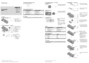
1. Parts list
18262d_1
Compressed-air supply plate
VABF- -P3A3- P5 ...
1 Plate
2 Seal
3 M5x12 screw
(1x)
(1x)
(4x)
18262d_3
End plate
VABE- -C P5
1 Plate
2 Seal
3 M5x12 screw
(1x)
(1x)
(4x)
18262d_2
Intermediate zone
supply module
VABF- -P1A3- P5 ...
1 Plate
2 O-ring
3 M6x20 screw
4 Slot nut
(1x)
(1x)
(2x)
(2x)
1826
2d_6
Not included in scope
of delivery:
5 Mounting rail
(1x)
IPM- - -40x80- PN 08 AL
As intended:
The compressed-air supply plate serves as a lateral supply port and seal
of the mounting rail
The end plate serves as seal for the mounting rail
The intermediate zone supply module serves as frontal, additional supply
port of the mounting rail.
Note
Select additional accessories from the catalogue
(e.g. mounting plate VAME- -MK). P5
For mounting of the mounting plates ( relevant assembly instructions).
2. Preassembly (for attachment of an intermediate zone supply module)
Note
To ensure an optimal compressed air supply when an intermediate zone
supply module is used.
Observe that:
The intermediate zone supply module should be set as closely as 1
possible to the centre
Several intermediate zone supply modules must be distributed evenly.1
The required distance from the mounting plates VAME- - P5 MK
( relevant assembly instructions).
Mark the position for the hole (A).
Drill the corresponding hole (A) mm. @12
Deburr the hole (A).
On each of both sides, cut a thread (M5, depth mm) into the 10
4 holes (B)
Remove all shavings from the mounting rail . 5
3. Mounting
3a. Mounting of the intermediate zone supply module
18262d_7
Note
To avoid mounting problems
during the assembly
sequence:
Remove the slot nuts 4
from the centre of the
mounting rail 5
( centre hole (A)).
Push the slot nuts into the mounting rail . 4 5
18262d_8
Place the O-ring in the 2
depression in plate . 1
Position the plate on the 1
mounting rail until the 5
hole (A) and thread (C) are
aligned.
Tighten the screws . 3
Comply with the permissible
tightening torque.
3b. Mounting of the compressed-air supply plate or end plate
18262d_4
Place the seal in the 2
opening (D).
Observe thereby the
mounting position
( magnifying glasses).
Fasten the plates on the 1
desired side to the mount-
ing rail with screws . 5 3
Observe the permissible
tightening torque.
18262d_5
5
1
2
3
1
2
3
1
2
3
4
2 Nm % _10
2 Nm % _10
5
4
A
3
1
2
D
2
1
3
5
B
A
2 Nm % _10
C
3
1
5
2
D


Produkt Specifikationer

Mærke: Festo
Kategori: Ikke kategoriseret
Model: VABE-P5-C

Har du brug for hjælp?

Hvis du har brug for hjælp til Festo VABE-P5-C stil et spørgsmål nedenfor, og andre brugere vil svare dig


Ikke kategoriseret Festo Manualer

Ikke kategoriseret Manualer

Nyeste Ikke kategoriseret Manualer