Festo VABM-B10-20-G38-6-P53 Manual

Festo Ikke kategoriseret VABM-B10-20-G38-6-P53

Læs gratis den danske manual til Festo VABM-B10-20-G38-6-P53 (1 sider) i kategorien Ikke kategoriseret. Denne vejledning er vurderet som hjælpsom af 10 personer og har en gennemsnitlig bedømmelse på 4.4 stjerner ud af 5.5 anmeldelser. Har du et spørgsmål om Festo VABM-B10-20-G38-6-P53, eller vil du spørge andre brugere om produktet?

Side 1/1
Assembly instructions (Original instructions)
8067341
1701c
[8067343]
†‡
Common supply manifold
VABM-B10-20-...-P53
Festo SE & Co. KG
73734 Esslingen
Germany
+49 711 347-0
www.festo.com
1. Applicable documents
All available documents for the product www.f
esto.com/pk
2. Safety
Switch off compressed air before mounting work.
Observe tigh
tening torques.
3. Intended use
Pneumatic linking of the valves.
4. Further info
rmation
Accessories for VABM www.fes
to.com/catalogue
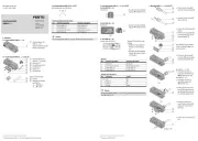
5. Scope of delivery
20260d_1
VABM-B10-20-...-P53
1 Common supply
manifold
2 Blanking plug B-3/8
3 Screw M3x40
1)2)
4 Screw M3x30
1)2)
5 Screw M4
(thread-cutting)
6 Mounting bracket
7 Seal
1)
(1x)
(1x)
(nx)
(nx)
(8x)
(2x)
(nx)
20260d_2
VABM-B10-20-...-P53-E
1 Common supply
manifold
2 Blanking plug B-3/8
3 Screw M3x40
1)2)
4 Screw M3x30
1)2)
5 Screw M4
(thread-cutting)
6 Mounting bracket
7 Seal
1)
(1x)
(1x)
(nx)
(nx)
(4x)
(1x)
(nx)
6. Not in scope of delivery
20260d_3
8 Solenoid valve
VUVS-... or
pneumatic valve
VUWS-...
1)
(nx)
1)
The number of screws , seals 3 4/7 and valves 8 is dependent on the available valve
positions.
2)
Number = 2 x available valve positions
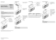
7. Mounting the mounting bracket 6
6
6
66
7a. VABM-B10-20-...-P53
20260d_4
Define alignment of
the common supply
manifold 1.
20260d_7
Place both mounting
brackets 6 on the common
supply manifold 1.
Tighten all screws 5. If you
screw it in again, use the
threads already present.
7b. VABM-B10-20-...-P53-E
20260d_5
Define alignment of
the common supply
manifold 1.
20260d_8
Place the mounting
bracket 6 on the common
supply manifold 1.
Tighten all screws 5. If you
screw it in again, use the
threads already present.
8. Mounting of blanking plugs 2
2
2
22
2026
0d_6
Screw the blanking plug 2
in at the desired position,
as required.
9. Mounting of valve 8
8
8
88
Information
Screws 4 can only be mounted with solenoid valves 8 VUVS-LK…-S.
20260d_9
/ Push screws 3 4 into the
drill holes of the valve 8.
Only screws 3 are
loss-protected.
Push seal 7 into channel 1
of the valve 8. Rotating
movement required during
mounting.
Place channel 1 of the
valve 8 onto the
opening (A).
Position the valve 8 on
the threads (B).
Tighten screws 3 4/ .
1
1
2
2
5
5
7
7
6
6
8
3 Nm _ 20 %
3 Nm _ 20 %
1.4 Nm _ 20 %
3
/
4
6
5
1
1
5
6
8
7
A B
1
1
2
8.5 Nm
_ 15 %
3
4
3
4


Produkt Specifikationer

Mærke: Festo
Kategori: Ikke kategoriseret
Model: VABM-B10-20-G38-6-P53

Har du brug for hjælp?

Hvis du har brug for hjælp til Festo VABM-B10-20-G38-6-P53 stil et spørgsmål nedenfor, og andre brugere vil svare dig