Festo VAEM-S6-S-FAS-4-4E Manual

Festo Ikke kategoriseret VAEM-S6-S-FAS-4-4E

Læs gratis den danske manual til Festo VAEM-S6-S-FAS-4-4E (2 sider) i kategorien Ikke kategoriseret. Denne vejledning er vurderet som hjælpsom af 14 personer og har en gennemsnitlig bedømmelse på 3.6 stjerner ud af 7.5 anmeldelser. Har du et spørgsmål om Festo VAEM-S6-S-FAS-4-4E, eller vil du spørge andre brugere om produktet?

Side 1/2
Montageanleitung (de)
726 147 / 2008-06NH
†‡
AS-I-Modul
VAEM-S6-S-FAS-4-4E/-8-8E
Festo SE & Co. KG
Postfach
D-73726 Esslingen
++49/(0)711/347-0
www.festo.com
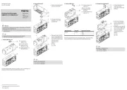
1. Teileliste
12803d_1
1 AS-I-Modul
VAEM-S6-S-FAS-…
2 Schutzkappe
Anschluss Out
3 Schutzkappe
Anschluss In
4 Erdungskabel
5 Ringkabelschuh
6 Schraube (selbst schneidend)
M4x8 (Torx T20)
7 Scheibe
B 4,3 DIN125
8 Sicherungsscheibe
M4
9 Blende
MPA-ASI-CPI
aJ Schraube (3x)
M4x38
Nicht im Lieferumfang:
aA Multipolknoten
VABE-S6…LT-C-…
aB Anschlussblock
CPX-AB-…
aC Schraube (4x)
(selbst schneidend)
Delta PT 30 x 32
Bestimmungsgemäß dient das AS-I-Modul 1 als Zubehörteil zur elektri-
schen Anschaltung für E/A-Bussysteme bei einer VTSA-Ventilinsel.
2. Montage
12803d_2
Verbinden Sie das AS-I-
Modul 1 und den Multipol-
knoten aA zur Funktions-
erdung mit dem Erdungs-
kabel 4 wie folgt:
Führen Sie die Schraube 6
durch die Scheibe 7, den
Kabelschuh 5 und die Si-
cherungsscheibe 8.
Drehen Sie die Schraube 6
fest, mit einem TORX-
Schraubendreher T20. Hal-
ten Sie das zulässige An-
ziehdrehmoment ein.
12803d_3
Platzieren Sie das AS-I-
Modul 1 auf dem Multipol-
knoten aA.
Drehen Sie die Schrauben aJ
fest. Halten Sie das zulässige
Anziehdrehmoment ein.
12803d_4
Platzieren Sie den An-
schlussblock aB auf dem
AS-I-Modul 1.
Drehen Sie die Schrauben aC
fest. Halten Sie das zulässige
Anziehdrehmoment ein.
12803d_5
Drücken Sie die Blende 9 in
den Anschlussblock aB.
12803d_6
Zum Anschließen:
Drehen Sie die Schutz-
kappen 2 und 3 an den
Anschlüssen IN / OUT herun-
ter.
1,5 Nm _ 20%
1 Nm 10% _
aA
8
7
6
2
5
4
9
aJ
3
1
1
aA
7
4
1 Nm 10% _
8
5
6
aA
1
aJ
aB
1
aC
9
aB
3
2
Assembly instructions (en)
726 147 / 2008-06NH
†‡
AS-i module
VAEM-S6-S-FAS-4-4E/-8-8E
Festo SE & Co. KG
Postfach
D-73726 Esslingen
++49/(0)711/347-0
www.festo.com
1. Parts list
12803d_1
1 AS-i module
VAEM-S6-S-FAS-…
2 Protective cap
Out connection
3 Protective cap
In connection
4 Earthing cable
5 Ring cable lug
6 Screw (self-tapping)
M4x8 (Torx T20)
7 Disc
B 4.3 DIN125
8 Retaining washer
M4
9 Orifice
MPA-ASI-CPI
aJ Screw (3x)
M4x38
Not included in scope of
delivery:
aA Multi-pin node
VABE-S6…LT-C-…
aB Manifold block
CPX-AB-…
aC Screw (4x)
(self-tapping)
Delta PT 30 x 32
The AS-i-module 1 is intended as an electrical accessory module for I/O bus
systems on a VTSA valve terminal.
2. Assembly
12803d_2
Connect the AS-i module 1
and the multi-pin node aA for
functional earthing to the
earthing cable 4 as follows:
Pass the screw 6 through
the disc 7, the cable lug 5
and the retaining washer 8.
Tighten screws 6 with a
TORX T20 screwdriver.
Maintain the permitted
tightening torque.
12803d_3
Place the AS-i-module 1 on
the multi-pin node aA.
Tighten screws aJ. Maintain
the permitted tightening
torque.
12803d_4
Place the manifold block aB
on the AS-i-module 1.
Tighten screws aC. Maintain
the permitted tightening
torque.
12803d_5
Press the orifice 9 into the
manifold block aB.
12803d_6
For connecting:
Unscrew the protective
caps 2 and 3 on the
IN/OUT connections.
1.5 Nm _ 20%
1 Nm 10% _
aA
8
7
6
2
5
4
9
aJ
3
1
1
aA
7
4
1 Nm 10% _
8
5
6
aA
1
aJ
aB
1
aC
9
aB
3
2


Produkt Specifikationer

Mærke: Festo
Kategori: Ikke kategoriseret
Model: VAEM-S6-S-FAS-4-4E

Har du brug for hjælp?

Hvis du har brug for hjælp til Festo VAEM-S6-S-FAS-4-4E stil et spørgsmål nedenfor, og andre brugere vil svare dig