INTRODUCTION
Thank you for choosing First Alert® for your Smoke and Carbon Monoxide Alarm needs. You
have purchased a state-of-the-art Smoke & Carbon Monoxide Alarm designed to help provide
you with early warning (Heads-Up) of a smoke and/or carbon monoxide danger. Please take
the time to read this manual and make the Smoke & Carbon Monoxide Alarm an integral part
of your family’s safety plan.
Alarm Features
• Voice Alerts with Heads-Up Warning: Friendly voice tells you what the danger is and its
location.
• Hardwire Interconnect: When one alarm sounds, all compatible alarms sound.
• Quick Connect Plug: Allows for easy installation. No need to rewire.
• Mobile alerts whether home or away
Installation Notes
• This unit will not alert hearing impaired residents. It is recommended that you install spe-
cial units which use devices like ashing strobe lights to alert hearing impaired residents.
• This unit must be powered by a 24-hour, 120VAC pure sine wave 60Hz circuit. Be sure the
circuit cannot be turned off by a switch, dimmer, or ground fault circuit interrupter. Failure
to connect this unit to a 24-hour circuit may prevent it from providing constant protection.
• Test this Smoke Alarm once a week. If the alarm ever fails to test correctly, have it replaced
immediately! If the alarm is not working properly, it cannot alert you to a problem.
• Install in accordance with installation instructions, applicable codes and ordinances and in
a manner acceptable to the authority having jurisdiction. Check with your local Fire Depart-
ment for current requirements in your area.
SC5 Wired Smart Smoke & Carbon
Monoxide Alarm
SMCO600NV-AC
Installation & Reference Manual
IMPORTANT! PLEASE READ CAREFULLY AND SAVE.
The warnings/limitations card and manual contains important information about your
Smoke Alarm’s operation. If you are installing this Alarm for use by others, you must leave
this manual—or a copy of it—with the end user.
Para el manual del usuario en español, por favor visite rstalert.com
Manufactured by
Resideo Technologies, Inc.
Scottsdale, AZ 85254
www.resideo.com
© 2024 Resideo Technologies, Inc. All Rights Reserved.
These products are manufactured by Resideo Technologies, Inc. and its aliates.
M08-0669-000 L2 7/24 Rev A
BASIC SAFETY INFORMATION
IMPORTANT!
• Dangers, Warnings, and Cautions alert you to important operating instructions or to potentially hazard-
ous situations. Pay special attention to these items.
• This smoke and co alarm is approved for use in single-family residences. It is NOT designed for
marine or RV use.
• This Alarm must have battery power to operate.
• This Smoke Alarm cannot operate without working batteries. Removing the batteries for any reason, or
failing to replace the batteries at the end of their service life, removes your protection.
• The Smoke Alarm will only indicate the presence of smoke that reaches the sensor.
• The Smoke Alarm is not designed to sense gas, heat or ames.
! WARNING!
• Installation of this unit must conform to the electrical codes in your area; Articles 210 and 300.3 (B) of
NFPA 70 (NEC), NFPA 72, NFPA 101; SBC (SBCCI); UBC (ICBO); NBC (BOCA); OTFDC (CABO), and any
other local or building codes that may apply. Wiring and installation must be performed by a licensed
electrician. Failure to follow these guidelines may result in injury or property damage.
• NEVER ignore any alarm. See “If Your Smoke Alarm Sounds” for more information on how to respond
to an alarm. Failure to respond can result in injury or death.
• The Silence Features are for your convenience only and will not correct a problem. See “Using the
Silence Features” for details. Always check your home for a potential problem after any alarm. Failure
to do so can result in injury or death.
• Never disconnect the power from an AC powered unit to stop an unwanted alarm. Doing so will
disable the unit and remove your protection. In the case of a true unwanted alarm open a window or
fan the smoke away from the unit.
• The alarm will reset automatically when it returns to normal operation. Never remove the batteries
from a battery operated unit to stop an unwanted alarm (caused by cooking smoke, etc.). Instead open
a window or fan the smoke away from the unit. The alarm will reset automatically.
! CAUTION!
• Connect this unit ONLY to other compatible units. See “How To Install This Smoke Alarm” for details.
Do not connect it to any other type of alarm or auxiliary device.
• Connecting anything else to this unit may damage it or prevent it from operating properly.
• Do not stand too close to the unit when the alarm is sounding. It is loud to wake you in an emergency.
Exposure to the horn at close range may harm your hearing.
• Do not paint over the unit. Paint may clog the openings to the sensing chambers and prevent the unit
from operating properly.
• Be aware of various situations against which the smoke alarm may not be effective, for example:
1. Fires where the victim is intimate with a aming initiated re; for example, when a person's clothes
catch re while cooking;
2. Fires where the smoke is prevented from reaching the smoke alarm due to a closed door or other
obstruction;
3. Incendiary res where the re grows so rapidly that an occupant's egress is blocked even with
properly located smoke alarms.
ABOUT SMOKE ALARMS
Types of Alarms
All these Smoke Alarms are designed to provide early warnings of res if located, installed and cared for as described
in the user’s manual, and if smoke reaches the Alarm. If you are unsure which type of Smoke Alarm to install, refer the
National Fire Protection Association (NFPA) Standard 72 (National Fire Alarm and Signaling Code) and NFPA 101 (Life
Safety Code). National Fire Protection Association, One Batterymarch Park, Quincy, MA 02269-9101. Local building
codes may also require specic units in new construction or in different areas of the home.
Battery (DC) operated Smoke Alarms: Provide protection even when electricity fails, provided the batteries are fresh
and correctly installed. Units are easy to install, and do not require professional installation. However, they do not
provide interconnected functionality.
AC powered Smoke Alarms: Can be interconnected so if one unit senses smoke, all units Alarm. They do not operate
if electricity fails. AC with battery (DC) back-up: will operate if electricity fails, provided the batteries are fresh and
correctly installed. AC and AC/DC units must be installed by a qualied electrician.
Smoke Alarms for solar or wind energy users and battery backup power systems: AC powered Smoke Alarms should
only be operated with true or pure sine wave inverters. Operating this Alarm with most battery-powered UPS (uninter-
rupted power supply) products or square wave or “quasi sine wave” inverters will damage the Alarm. If you are not sure
about your inverter or UPS type, please consult with the manufacturer to verify.
Smoke Alarms for the hearing impaired: Special purpose Smoke Alarms should be installed for the hearing impaired.
They include a visual Alarm and an audible Alarm horn, and meet the requirements of the Americans With Disabilities
Act. Can be interconnected so if one unit senses smoke, all units Alarm.
Smoke Alarms are not to be used with detector guards unless the combination has been evaluated and found suitable
for that purpose.
All First Alert® Smoke Alarms conform to regulatory requirements, including UL217 and are designed to detect
particles of combustion. Smoke particles of varying number and size are produced in all res.
Ionization technology is generally more sensitive than photoelectric technology at detecting small
particles, which tend to be produced in greater amounts by aming res, which consume combustible
materials rapidly and spread quickly. Sources of these res may include paper burning in a wastebasket,
or a grease re in the kitchen.
Photoelectric technology is generally more sensitive than ionization technology at detecting large
particles, which tend to be produced in greater amounts by smoldering res, which may smolder for hours
before bursting into ame. Sources of these res may include cigarettes burning in couches or bedding.
For maximum protection, use both types of Smoke Alarms on each level and in every bedroom of your home.
FIRE SAFETY TIPS
Follow safety rules and prevent hazardous situations:
1. Use smoking materials properly. Never smoke in
bed.
2. Keep matches or lighters away from children;
3. Store ammable materials in proper containers;
4. Keep electrical appliances in good condition and
don’t overload electrical circuits;
5. Keep stoves, barbecue grills, replaces and chim-
neys grease- and debris-free;
6. Never leave anything cooking on the stove
unattended;
INSTALLATION
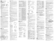
WHERE TO INSTALL THIS Alarm
Minimum coverage for Smoke Alarms, as recommended by the National Fire Protection Association
(NFPA), is one Smoke Alarm on every oor, in every sleeping area, and in every bedroom (See “Regu-
latory Information For Smoke Alarms” for details on the NFPA recommendations).
For CO Alarms, the National Fire Protection Association (NFPA) recommends that a CO Alarm
should be centrally located outside of each separate sleeping area in the immediate vicinity of the
bedrooms. For added protection, install additional CO Alarms in each separate bedroom, and on
every level of your home.
NOTE: For added protection, install an additional Smoke/CO Alarm at least 15 feet (4.6 meters) away
from the furnace or fuel burning heat source where possible. In smaller homes or in manufactured
homes where this distance cannot be maintained, install the Alarm as far away as possible from the
furnace or other fuel burning source. Installing the Alarm closer than 15 feet (4.6 meters) will not
harm the Alarm, but may increase the frequency of unwanted alarms.
! WARNING!
This product is intended for use in ordinary indoor locations of family living units. It is not designed
to measure compliance with Occupational Safety and Health Administration (OSHA) commercial or
industrial standards.
In general, install combination Smoke and Carbon Monoxide Alarms:
• On every level of your home, including nished attics and basements.
• Inside every bedroom, especially if people sleep with the door partly or completely closed.
• In the hall near every sleeping area. If your home has multiple sleeping areas, install a unit in each.
If a hall is more than 40 feet (12 meters) long, install a unit at each end.
• At the top of rst-to-second oor stairs and at the bottom of the basement stairs.
• For additional coverage, install Alarms in all rooms, halls, and storage areas, where temperatures
normally remain between 40˚ F and 100˚ F (4.4˚ C and 37.8˚ C).
• When installing on the ceiling, place the Alarm as close to the center as possible.
• When installing on the wall, the top edge of Smoke Alarms should be placed between 4 inches
(102 mm) and 12 inches (305 mm) from the wall/ceiling line.
• In either case, install at least 4 inches (102 mm) from where the wall and ceiling meet. See “Avoid-
ing Dead Air Spaces” for more information.
NOTE: For any location,
make sure no door or
other obstruction could
keep carbon monoxide
or smoke from reaching
the Alarm.
Smoke Alarm
One on every level and
in every bedroom
Fire Extinguisher
One on every level, plus
Carbon Monoxide
Alarm
One on every level and in
every bedroom
WHERE NOT TO INSTALL THIS ALARM
FOR BEST PERFORMANCE, IT IS RECOMMENDED YOU AVOID INSTALLING SMOKE/CO
ALARMS IN THESE AREAS:
• In garages, furnace rooms, crawl spaces and unnished attics. Avoid extremely dusty, dirty
or greasy areas.
• Where combustion particles are produced. Combustion particles form when something
burns. Areas to avoid include poorly ventilated kitchens, garages, and furnace rooms. Keep
units at least 10 feet (3 meters) from the sources of combustion particles (stove, furnace,
water heater, space heater) if possible. In areas where a 20-foot (6 meter) distance is not
possible – in modular, mobile, or smaller homes, for example – it is recommended the
Smoke Alarm be placed as far from these fuel-burning sources as possible. The placement
recommendations are intended to keep these Alarms at a reasonable distance from a
fuel-burning source, and thus reduce “unwanted” Alarms. Unwanted Alarms can occur if
a Smoke Alarm is placed directly next to a fuel-burning source. Ventilate these areas as
much as possible.
• Within 5 feet (1.5 meters) of any cooking appliance. In air streams near kitchens. Air cur-
rents can draw cooking smoke into the smoke sensor and cause unwanted Alarms.
• In extremely humid areas. This Alarm should be at least 10 feet (3 meters) from a shower,
sauna, humidier, vaporizer, dishwasher, laundry room, utility room, or other source of high
humidity.
• In direct sunlight.
• In turbulent air, like near ceiling fans or open windows. Blowing air may prevent smoke
from reaching the sensors.
• In areas where temperature is colder than 40˚ F (4.4˚ C) or hotter than 100˚F (37.8˚ C).
These areas include non air-conditioned crawl spaces, unnished attics, uninsulated or
poorly insulated ceilings, porches, and garages.
• In insect infested areas. Insects can clog the openings to the sensing chamber.
• Less than 12 inches (305 mm) away from uorescent lights. Electrical “noise” can interfere
with the sensor.
• In “dead air” spaces.
AVOIDING DEAD AIR SPACES
“Dead air” spaces may prevent smoke from reaching the Smoke Alarm. To avoid dead air
spaces, follow installation recommendations below.
On ceilings, install Smoke Alarms as close to the center of the ceiling as possible. If this is not
possible, install the Smoke Alarm at least 4 inches (102 mm) from the wall or corner.
For wall mounting (if allowed by building codes), the top edge of Smoke Alarms should be
placed between 4 inches (102 mm) and 12 inches (305 mm) from the wall/ceiling line, below
typical “dead air” spaces.
On a peaked, gabled, or cathedral ceiling, install the rst Smoke Alarm within 3 feet (0.9
meters) of the peak of the ceiling, measured horizontally. Additional Smoke Alarms may be re-
quired depending on the length, angle, etc. of the ceiling’s slope. Refer to NFPA 72 for details
on requirements for sloped or peaked ceilings.
HOW TO INSTALL THIS ALARM
IMPORTANT!
This Smoke/CO Alarm is designed to be mounted on any standard wiring junction box up to
a 4-inch (10 cm) size, on either the ceiling or wall (if allowed by local codes). Read “Where to
Install This Alarm” and “Where This Alarm Should Not Be Installed” before you begin installa-
tion.
Tools you will need: needle-nose pliers or utility knife, standard athead screwdriver, wire
strippers.
! WARNING!
Make sure the Alarm is not receiving excessively noisy power. Examples of noisy power
could be major appliances on the same circuit, power from a generator or solar power,
light dimmer on the same circuit or mounted near uorescent lighting. Excessively noisy
power may cause damage to your Alarm.
FOLLOW THESE SIMPLE STEPS
The basic installation of this Smoke/CO Alarm is similar whether you want to install one Alarm, or intercon-
nect more than one Alarm.
1. Make the wiring connections (below).
7. Keep portable heaters and open ames, like candles,
away from ammable materials;
8. Don’t let rubbish accumulate. Keep Alarms clean, and
test them weekly. Replace Alarms immediately if they
are not working properly. Smoke Alarms that do not
work cannot alert you to a re. Keep at least one work-
ing re extinguisher on every level, and an additional
one in the kitchen. Have re escape ladders or other
reliable means of escape from an upper level in case
stairs are blocked;
9. Have an escape plan and practice it regularly.
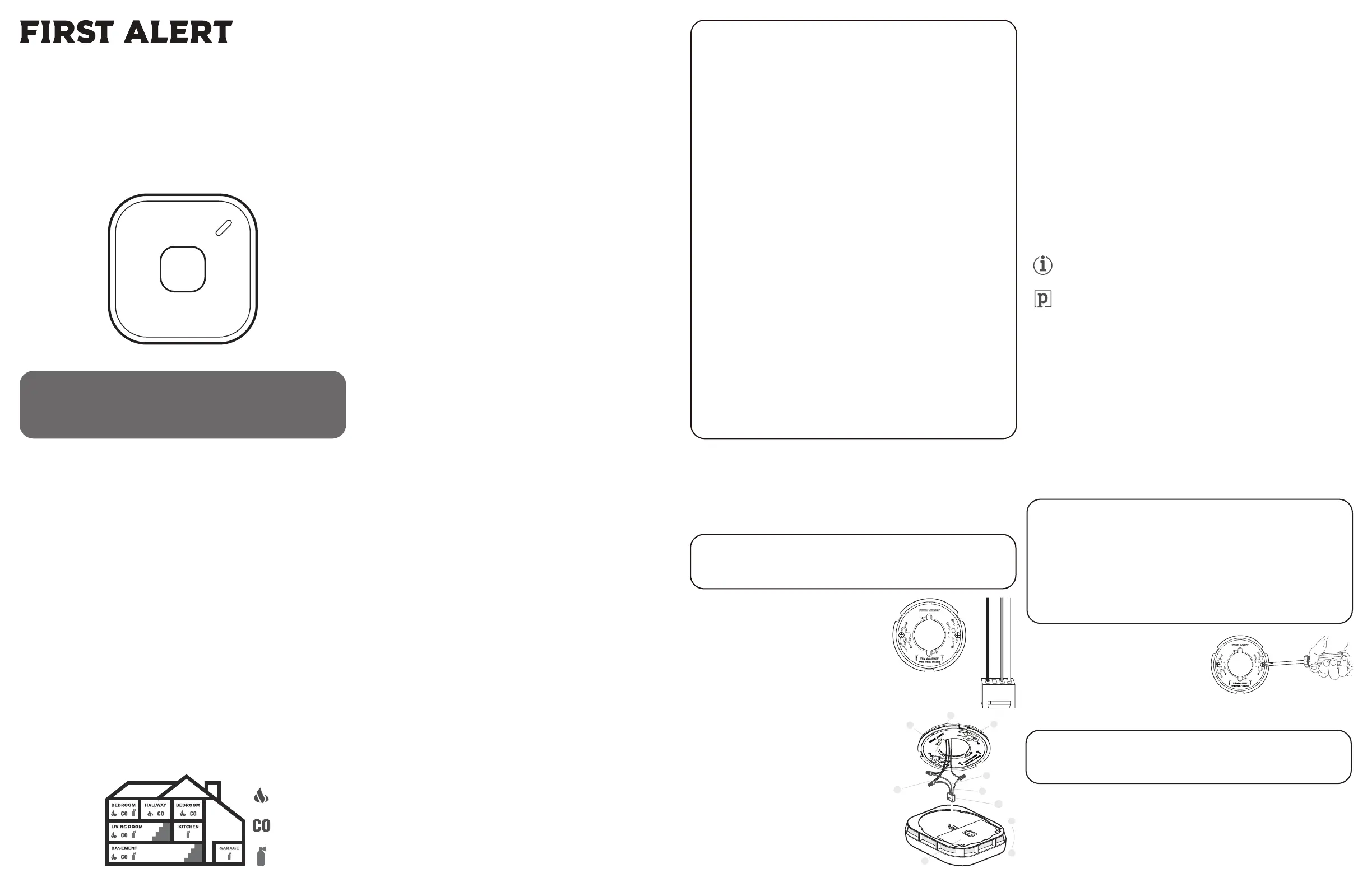
THE PARTS OF THIS ALARM
The Mounting Bracket: The mounting bracket installs
onto the junction box. It has a variety of screw slots to
t most boxes.
The Power Connector: The power connector plugs into
a power input block on the Alarm. It supplies the unit
with AC power.
• The black wire is “hot.”
• The white wire is neutral.
• The orange wire is used for interconnect.
If you need to remove the power connector, turn POWER
OFF rst. Insert a at screwdriver blade between the
power connector and the security tab inside the power
input block. Gently pry back the tab and pull the connec-
tor free.
THE PARTS OF THIS SMOKE/CO ALARM
1. Mounting Bracket
2. Mounting Slots
3. Hot (Black) AC Wire
4. Neutral (White) AC Wire
5. Interconnect (Orange) Wire
6. Quick-Connect Power Connector
7. Turn this way to remove from bracket
8. Turn this way to attach to bracket
9. Battery Compartment Door
1
2
3
5
4
8
7
6
2
9
NOTE: TURN POWER OFF AT THE BREAKER BOX BEFORE MAKING CONNECTIONS
BELOW.
STAND-ALONE ALARM ONLY:
• Connect the white wire on the power connector to the neutral wire in the junction box.
• Connect the black wire on the power connector to the hot wire in the junction box.
• Tuck the orange wire inside the junction box. It is used for interconnect only.
INTERCONNECTED UNITS ONLY:
• Strip off about 1/2” (12 mm) of the plastic coating on the orange wire on the power connector.
• Connect the white wire on the power connector to the neutral wire in the junction box.
• Connect the black wire on the power connector to the hot wire in the junction box.
• Connect the orange wire on the power connector to the interconnect wire in the junction box.
• Repeat for each unit you are interconnecting. Never connect the hot or neutral wires in the junction
box to the orange interconnect wire.
STAND-ALONE ALARM ONLY:
• If you are only installing one Alarm, restore power to the junction box.
INTERCONNECTED UNITS ONLY:
• If interconnecting multiple Alarms, repeat steps 1-6 for each Alarm in the series. When nished,
restore power to the junction box.
2. Check all connections.
3. Feed the wire connector through the hole in the mounting
bracket and attach the mounting bracket to the mounting
surface. NOTE: Do not overtighten screws!
4. Insert the wiring harness connector to the receptacle on
the device.
5. If not done so already, activate the battery back-up by
removing the battery tab.
6. Position the base of the Alarm over the mounting bracket,
and turn the Alarm clockwise (right) until the unit is in place. If wall mounted, adjust unit so words are
level.
7. Turn AC power back on. Under normal operation, the Green power indicator light will shine continuously.
8. If the Green power indicator light does not light, TURN OFF POWER TO THE JUNCTION BOX and recheck
all connections. If all connections are correct and the Green power indicator still does not light when you
restore the power, the device should be replaced immediately.
9. Test each Alarm. Press and hold the Test/Silence button until the unit Alarms. When testing a series of
interconnected units, each unit must be tested individually. Make sure all units alarm when tested.