FOX ESS H1-3.7-E Manual
Læs gratis den danske manual til FOX ESS H1-3.7-E (44 sider) i kategorien Solpanel. Denne vejledning er vurderet som hjælpsom af 26 personer og har en gennemsnitlig bedømmelse på 4.8 stjerner ud af 13.5 anmeldelser.
Har du et spørgsmål om FOX ESS H1-3.7-E, eller vil du spørge andre brugere om produktet?

Produkt Specifikationer
| Mærke: | FOX ESS |
| Kategori: | Solpanel |
| Model: | H1-3.7-E |
Har du brug for hjælp?
Hvis du har brug for hjælp til FOX ESS H1-3.7-E stil et spørgsmål nedenfor, og andre brugere vil svare dig
Solpanel FOX ESS Manualer


Solpanel Manualer
- Mestic
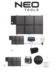
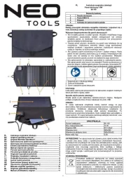
- NEO Tools
- Yingli Solar
- Furrion
- Anker
- Segway
- BenQ
- NEP
- Deye
- KKT Kolbe
- Velleman
- Sunware
- Osram
- Sungrow
- APsystems
Nyeste Solpanel Manualer