Prepared in Germany • Subject to change, errors
excepted • A pdf version is available on the Internet
All trademarks, registered trademarks, logos, prod-
uct names, and company names are the property of
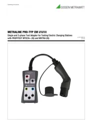
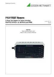
1-/3-phase test adapter for testing the
effectiveness of protective measures at
e-charging points for the METRALINE MF
ranges (as for example medicine and agriculture).
Measurements in dangerous proximity of electrical
systems are only to be carried out in compliance with
the instructions of a responsible electronics techni-
If the operator’s safety is no longer ensured, the
instrument is to be put out of service and protected
against use. The safety is no longer insured, if the
• does not carry out the desired measurements,
• has been stored for too long under unfavourable
• has been subjected to mechanical stress during
The instrument may only be used within the operating
ranges as specied in the technical data section.
Avoid any heating up of the instrument by direct sun-
light to ensure perfect functioning and long instrument
The opening of the instrument for fuse replacement,
for example, may only be carried out by professionals.
Prior to opening, the instrument has to be switched off
and disconnected from any current circuit.
The instrument may only be used under those condi-
tions and for those purposes for which it was conceived.
For this reason, in particular the safety references,
the technical data including environmental conditions
and the usage in dry environments must be followed.
When modifying or changing the instrument, the operation-
al safety is no longer ensured.
Please read this important information!
2.1 Intended use / Use for intended purpose
The METRALINE EVSE IT is a test adapter (accessory) to
support all relevant measurements of the METRALINE MF.
It is connected between the EVSE charging point (Type-2
connector) and the measurement inputs of the METRALINE
MF. All wires of the charging connector are available: L1,
L2, L3, N, PE, CP and PP.
This allows to perform typical measurements: voltage, fre-
quency, phase indication, phase sequence, various RCD
tests and measurements, insulation resistance, low ohm
measurements, line and loop impedances, etc.
Safety of the user, as well as that of the instrument, is only
assured when it’s used for its intended purpose.
2.2 Use for other than intended purpose
Using the instrument for any purposes other than those
described in these instrument operating instructions is con-
trary to use for intended purpose. Use for purposes other
than those intended may result in unforeseeable damage!
2.3 Liability and guarantee
The warranty provided by Gossen Metrawatt GmbH, and
its liability, are governed by the applicable contractual and
mandatory statutory provisions.
DANGER! Dangerous voltage. Danger of electrical
Note! Important information.
1 Operating instructions (this document)
Please check the scope of delivery for completeness and
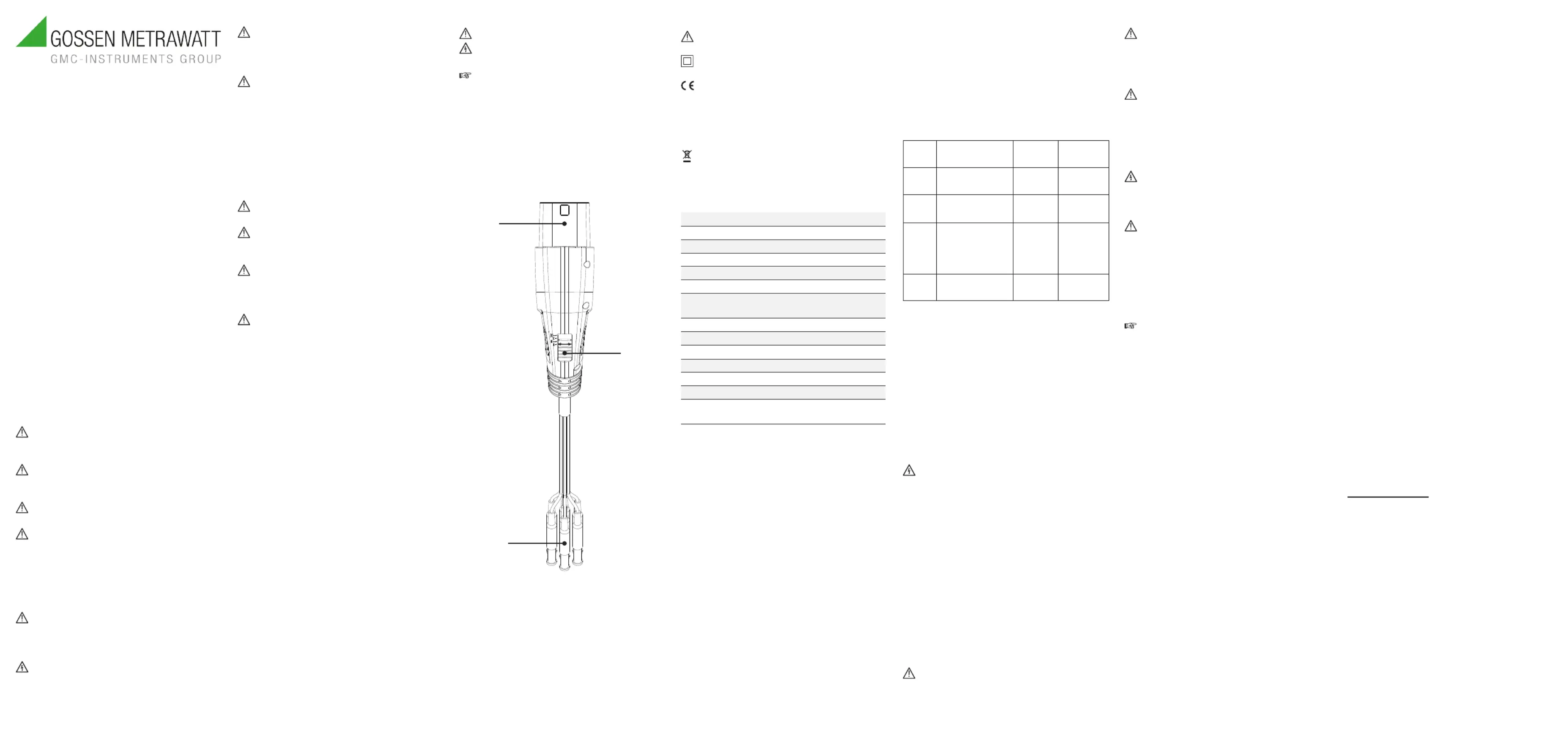
Operation elements and connectors:
2. Slider switch for CP mode selection
3. Test leads with 4 mm safety plugs for L1, L2, L3, N, PE,
The adapter is equipped with 1.5 m test leads.
4.3 Symbols on the instrument
Warning of a potential danger. Read and follow the
Continuous double or reinforced insulation category II
(IEC 536 / DIN EN 61140).
Conformity symbol, the instrument com-
plies with the valid EU directives.
It complies with the EMC Directive (2014/30/EU), DIN
EN IEC 61326, the Low Voltage Directive (2014/35/
EU), DIN EN 61010-1 and DIN EN 61010-031.
You can nd the CE declaration on our website.
The instrument may not be disposed of with house-
hold trash. You are required to comply with all appli-
cable local regulations. Further information regarding
disposal can be found on our website.
Input voltage: 230 V / 400 V 3~ 50 / 60 Hz
Measurement category: CAT II 300 V
Mains socket rating: max. 10 A
PP simulation: internally congured for 32 A
CP simulation: states A, B, C
Error simulation: CP error “E”
Test connector type: IEC 62196-2 Type 2 male
Working temperature: 0 … +40 ºC
Storage temperature: –10 … +50 ºC
Humidity: 0 … 80 % relative humidity
1. Connect the needed 4 mm test leads of the METRALINE
EVSE IT to your METRALINE MF.
2. Select CP mode “A” with the slider switch.
3. Connect METRALINE EVSE IT to the Type 2 connector
4. Select CP mode “B” with the slider switch, the charging
point should show “ready to charge”.
5. Select CP mode “C” with the slider switch, the charging
6. Perform all measurements in active stage of the
charging point (voltage and similar).
Refer to the METRALINE MFproduct documentation.
7. After you completed all your measurements
select CP Mode “A” with the slider switch to stop
8. Unplug METRALINE EVSE IT from the charging point.
5.2 Proximity Pilot (PP) state (cable simulation)
The METRALINE EVSE IT is designed in such a way
(220 Ω between PP and PE) that it provides a 32 A current
5.3 Control Pilot (CP) state (vehicle simulation)
Using the CP mode slider switch, various vehicle states can
be simulated. Vehicle states are simulated through different
resistances connected between CP and PE conductors.
The correlation between resistance and vehicle states is
shown in the table below.
5.4 CP Signal output terminals
The CP output terminals are short connected to the CP
and PE conductors of the tested charging station via the
test cable. Use an oscilloscope to check the waveform and
amplitude of the CP signal.
The Control Pilot function uses Pulse Width Modulation
(PWM) to code communication between a vehicle and
charging station. The duty cycle of the PWM signal denes
the possible available charging current, while the amplitude
denes the charger state.
For details of the communication protocol refer to DIN EN
IEC 61851-1 and the manufacturer’s documentation of the
If the charging station is wired incorrectly,
low signal CP test terminals may receive high,
life-threatening voltage.
5.5 CP Error “E” simulation
The “E”-CP error simulation can be realized by pushing
the slider switch into (spring loaded) position [E]. This will
simulate the behaviour of a charging station when there is a
short circuit between CP and PE through the internal diode
(acc. to DIN EN IEC 61851-1).
In case of an CP error (“E” is pushed), the expected result
is an abortion of the charging process and a new charging
The measuring terminals (no. 1 and 2 in the device over-
view) are directly connected to the L1, L2, L3, N and PE
conductors of the tested charging station.
The measuring terminals must only be used for
measurements. It is forbidden to draw current over a
longer period or supply anything else.
An appropriate measurement instrument is required.
Damage to the product and measuring error due to
Store the instrument in a protected location and only
within the limits of permissible ambient conditions.
Damage to the product and measuring error.
Transport the instrument only within the limits of per-
missible ambient conditions (temperature, humidity.
Only transport the instrument with sufcient protection.
Prior to cleaning, ensure that instrument is
switched off and disconnected from external volt-
age supply and any other instruments connected
(such as DUTs, control instruments, etc.).
Never use acid detergents or dissolvent for cleaning.
If the instrument is dirty after daily usage, it is advised
to clean it by using a humid cloth and a mild household
If your instrument requires repair, please contact our service
Loss of warranty and guarantee claims
Unauthorized modication of the instrument is prohib-
ited. This also includes opening the instrument. If it
can be ascertained that the tester has been opened
by unauthorized personnel, no guarantee claims
can be honored by the manufacturer with regard to
personal safety, measuring accuracy, compliance
with applicable safety measures or any consequential
The instrument may only be repaired or opened by au-
thorized, qualied personnel who are familiar with the as-
sociated dangers. Original replacement parts may only be
installed by authorized, qualied personnel.
9 Contact, Support and Service
Gossen Metrawatt GmbH can be reached directly
and simply – we have a single number for everything!
Whether you require support or training, or have an indi-
vidual inquiry, we can answer all of your questions here:
Monday to Thursday: 8 a.m. to 4 p.m.
Or contact us by e-mail at: info@gossenmetrawatt.com
Do you prefer support by e-mail?
Measuring and Test Technology:
support@gossenmetrawatt.com
Industrial Measuring Technology:
support.industrie@gossenmetrawatt.com
Please contact GMC-I Service GmbH for repairs, replace-
ment parts and calibration
Beuthener Str. 41, 90471 Nürnberg, Germany
service@gossenmetrawatt.com
https://www.gmci-service.com/en/
1 DAkkS calibration laboratory per DIN EN ISO/
IEC 17025 accredited by the Deutsche Akkred-
itierungsstelle GmbH under reference number
9 Contact, Support and Service
Read and follow these instructions carefully and completely
in order to ensure safe and proper use.
The instructions must be made available to all persons who
Keep for future reference.
Carefully and completely read and adhere to the
product documentation for the associated test/meas-
Use the product only for its intended purpose in ac-
cordance with this documentation and the documen-
tation for the associated test/measuring instrument.
The device may only be used by qualied electricians
The products and accessories of Gossen Metrawatt
GmbH are designed to ensure optimum compatibil-
ity with the Gossen Metrawatt GmbH products that
are expressly provided for them. Unless otherwise
expressly conrmed in writing by Gossen Metrawatt
GmbH, they are not intended and suited for use with
The respective accident prevention regulations
established by the professional associations for elec-
trical systems and equipment must be strictly met at
In order to avoid electrical shock, the valid safety and
VDE regulations regarding excessive contact voltag-
es must receive utmost attention, when working with
voltages exceeding 120 V (60 V) DC or 50 V (2 V)
rms AC. The values in brackets are valid for limited